Autosite_Users_Manual.pdf - 第77页
Operation AutoSite User Manual 3-19 Preventive Maintenance Conductive Pad The conductive pa d, the material th e MatchBook rest s on, should be k ept free of dirt to keep yields high an d prolong the life of the pad. We …
Operation
3-18 AutoSite User Manual
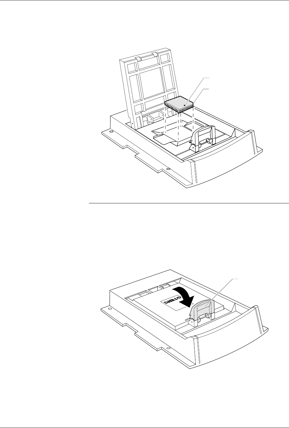
4. Insert the device into the MatchBook, as shown in Figure 3-13. Make
sure you insert the device according to the alignment diagram on the
MatchBook. Close the MatchBook.
Note: Position the device so pin 1 is near to the retaining clip. There is a small
dot molded into each MatchBook to help you align your device. Each
MatchBook also has a beveled corner to help you align devices with a
chamfered corner to indicate pin 1.
5. Finally, close the MatchBook and press the retaining latch forward
with your thumb until the latch snaps into place, as shown in
Figure 3-14.
Removing a Device
From a MatchBook
To remove a device from the MatchBook, unsnap the retaining latch,
open the MatchBook, and lift out the device.
Figure 3-13
Inserting a Device into the PLCC
Base
Figure 3-14
Closing the MatchBook
0538-3
CHAMFERED
CORNER
PIN 1
0539-4
44 PIN PLCC
RETAINING LATCH

Operation
AutoSite User Manual 3-19
Preventive Maintenance
Conductive Pad
The conductive pad, the material the MatchBook rests on, should be kept
free of dirt to keep yields high and prolong the life of the pad. We
recommend that you inspect and clean the pad at least every 1000 device
insertions or monthly, whichever comes first.
Note: After a number of insertions, you may notice an indentation in the middle
of the conductive pad. The indentation is normal and does not degrade the
contact resistance or the performance of the MatchBook. It is also normal
for the pad to show signs of discoloration as it is used.
The life of the pad is dependent on proper care as well as the pin count
and package type of the device being used. Not all devices have the same
tolerances, and use of each device type may result in different life cycles
for the pad. If you experience an increase in device insertion errors or
continuity errors, or if you experience a sudden drop in programming
yields, the pad may need to be replaced.
Cleaning
Blow air over the pad to clean it. If you use compressed air, direct the air
stream from the front or back of the Base.
Note: To avoid lifting the pad off the circuit board, do not blow air from the side
of the pad.
To further clean the pad, apply a small amount of isopropyl alcohol on a
cotton swab and gently wipe off the pad to dislodge dirt. Make sure the
pad is clear of any cotton filaments left over after cleaning.
CAUTION: Do not clean the pad with any petroleum- or freon-based
products. These substances will cause premature
deterioration of the pad material.
Replacement Pad Kits
The Base has been designed to allow you to replace the pads quickly and
easily and to minimize downtime. To order a replacement pad kit,
contact Data I/O Customer Support as listed in the Preface.
SPA Block and Base
For optimal performance, keep the SPA block (see Figure 3-6) and bases
clean. The following messages during device operations could result
from dirt in the SPA block or base adapter.
ID Error
Continuity Error
Base Adapter not Installed
Device Insertion Error
Overcurrent Error
Base/Adapter Relay Failure
SPA Block Cleaning
To avoid error conditions caused by dirty or worn SPA blocks, we
recommend that you perform the following preventive maintenance
procedures.
• Keep the SPA block covered with a base or programming module
when not in use. To prevent base adapters from contaminating the
SPA block, store them in an uncontaminated area.

Operation
3-20 AutoSite User Manual
• Each time you remove or replace a programming module, clean the
SPA block with a brush.
• Inspect the SPA block and base adapter for dirt weekly. Follow the
steps below to clean the SPA block.
1. Blow compressed air across the SPA block.
2. Mildly dampen a small section of a lint-free cloth with a DeOxit
pen (Data I/O P/N 570-5500-901) and gently rub the dampened
cloth across all the pins on the SPA block.
3. Using a clean section of the lint-free cloth, gently wipe the surface
again.
4. To ensure that all pins are properly positioned in their
receptacles, push a programming module down on the SPA pins
a few times and check that the pins spring up to their normal
upright position.
Base Cleaning
Weekly inspect the bases for dirt. Clean the surface, including the
underside, with filtered compressed air. Clean with a lint-free cloth
dampened with DeoxIT if needed.
Isolating Programming Problems
If you are experiencing less than optimal yields when programming a
DIP or PLCC device, we suggest that you remove the AutoSite pin driver
head from the handler and try programming the device in the DIP or
PLCC Base.
If the device programs successfully in the Base, there could a problem
with the handler or with the programming module supplied by the
handler manufacturer. Refer to your handler manual for cleaning,
maintenance, and testing information.
If you experience programming problems when programming the device
in the Base, try to isolate the nature of the problem. For example, does the
problem occur during programming or during post-programming
testing? If you are unable to correct the problem yourself, contact
Data I/O Customer Support as listed in the Preface of this manual.
Updating the MSM (Mass Storage Module)
The Mass Storage Module is an internal hard drive that can be installed in
AutoSite. The Mass Storage Module allows you to store system and
algorithm files in the programmer, which can speed up the start-up and
disk access routines.
Installation
The MSM comes installed in all new AutoSites. If your older AutoSite
does not have an MSM installed, you can purchase one for your AutoSite.
Installation instructions are shipped with the Mass Storage Module.