Autosite_Users_Manual.pdf - 第59页
AutoSite User Manual 3-1 Operation This chapter describes how to perform various day-to-day procedures on AutoSite, includ ing the followin g: • Starting AutoSite .................. ................. ................. ..…
Setup and Installation
2-36 AutoSite User Manual
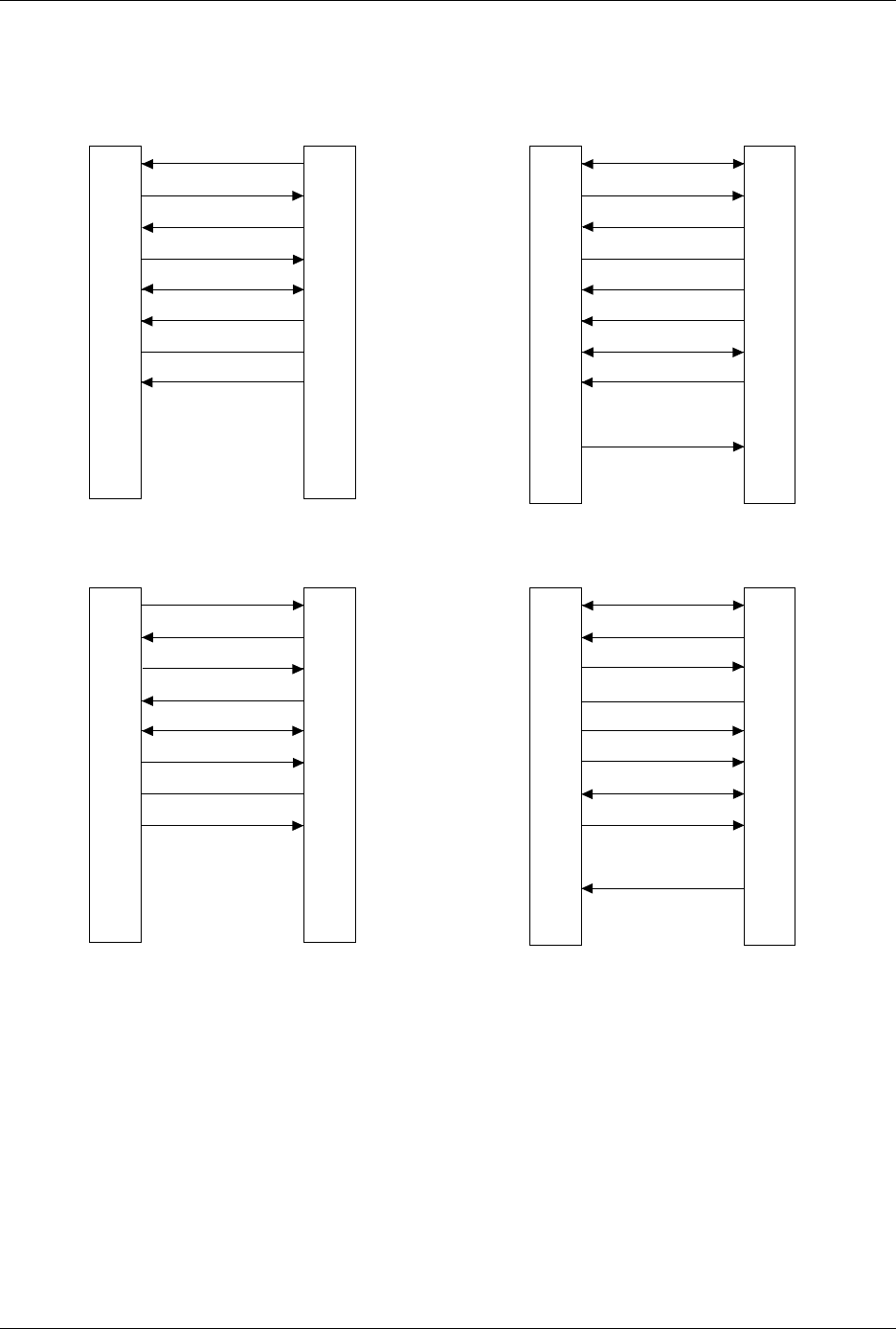
Figure 2-24
Pin Designations for RS-232C Serial Port Connection
1
2
3
4
5
6
7
8
9-19
20
21-25
1
2
3
4
5
6
7
8
20
PROTECTIVE GND
DATA
DATA
RTS (HELD HIGH)
CTS
DSR
SIGNAL GND
DCD
DTR
NC
GND
RECEIVE
TRANSMIT
RTS
CTS
DSR
GND
DCD
DTR
TRANSMIT
RECEIVE
25 PIN
AUTOSITE (DTE)
25 PIN
MODEM (DCE)
1
2
3
4
5
6
7
8
9-19
20
21-25
1
2
3
4
5
6
7
8
20
PROTECTIVE GND
DATA
DATA
RTS (HELD HIGH)
CTS
DSR
SIGNAL GND
DCD (HELD HIGH)
DTR
NC
NC
GND
TRANSMIT
RECEIVE
RTS
CTS
DSR
GND
DCD
DTR
RECEIVE
TRANSMIT
25 PIN
AUTOSITE (DCE)
25 PIN
TERMINAL (DTE)
1373-1
The minimum hookup includes Pins 2, 3, and 7.
Pins 1 and 7 are tied together.
NC
8
2
3
20
7
6
4
5
1
9-19
21-25
1
2
3
4
5
6
7
8
9
DCD
DATA
DATA
DTR
SIGNAL GND
DSR
RTS (HELD HIGH)
CTS
DCD
RECEIVE
TRANSMIT
DTR
GND
DSR
RTS
CTS
TRANSMIT
RECEIVE
25 PIN
AUTOSITE (DTE)
9 PIN
MODEM (DCE)
NC
NC
NC
8
2
3
20
7
6
4
5
1
9-19
21-25
1
2
3
4
5
6
7
8
9
DCD
DATA
DATA
DTR
SIGNAL GND
DSR
RTS (HELD HIGH)
CTS
DCD
TRANSMIT
RECEIVE
DTR
GND
DSR
RTS
CTS
RECEIVE
TRANSMIT
25 PIN
AUTOSITE (DCE)
9 PIN
TERMINAL (DTE)
NC
NC
NC
NC
NC

AutoSite User Manual 3-1
Operation
This chapter describes how to perform various day-to-day procedures on
AutoSite, including the following:
• Starting AutoSite .....................................................................................3-2
• Changing a Programming Module.......................................................3-2
• Changing a Programming Module on a ProMaster 2000...........3-3
• Changing a Programming Module on a ProMaster 3000,
7000, or 7500......................................................................................3-8
• Inserting a DIP or PLCC Base..............................................................3-13
• Removing a Base....................................................................................3-15
• Inserting DIP Devices ..........................................................................3-16
• Using MatchBooks with PLCC Devices.............................................3-17
• Isolating Programming Problems.......................................................3-20
• Adding a New Programming Module to AutoSite..........................3-21
• Performing a Self-Test..........................................................................3-22
• Manipulating Keep Current Algorithm Files....................................3-24
3

Operation
3-2 AutoSite User Manual
Starting AutoSite
To prepare AutoSite for a session, follow the procedure below.
Note: If you have not used AutoSite for a while, or if you suspect AutoSite might
have been moved from one area to another, follow the procedure below
before you use AutoSite.
1. Ensure that AutoSite is set up as described in Chapter 2, “Setup and
Installation.”
2. Select and insert a programming module (or Base) into the pin driver
head. Make sure the programming module (or Base) is locked in
place.
3. Connect the pin driver head to the handler.
4. Power up AutoSite. (The powerup operation is described in detail on
page 2-28.)
5. Verify that AutoSite and the controlling software are communicating.
You are now ready to begin a session on AutoSite.
Changing a Programming Module: Overview
The procedure for changing a programming module depends on the
manufacturer of the handler you are using with AutoSite. See the
documentation supplied with your handler for information on changing
a programming module.
To prevent damage to AutoSite and to make changing programming
modules easier, we suggest that you keep the following items in mind
while changing a programming module:
• Make sure the handler is idle
• Wear a properly grounded antistatic wrist strap while working with
the programming module and the pin driver head
• Do not touch the gold pins exposed when you remove a
programming module from the pin driver head
• Do not block the fan on the side of the pin driver head
• If necessary, disconnect the 50-pin and 68-pin cables from the pin
driver head to gain better access to the pin driver head
• Do not use the device socket or connectors on the programming
module as a leverage point
• Store programming modules in a static safe area when not in use or
when removed from the pin driver head
Note: You may need to change hardware on your handler when you change
programming modules on AutoSite. See your handler manual for more
information.