DECAN_S1_Operation_EN.pdf - 第51页
It ems t o b e inspe ct e d du r ing p r oduction Chap ter 4 Nex t Generation, Multi- Funct ional Placer DE CAN S 1 Ope ra tio n Han db oo k 4-6 This chapter describes the methods for temporary stop of the machine(Contin…
Items to be inspected during production
Chapter 4
Next Generation, Multi-Functional Placer
DECAN S1 Operation Handbook
4-5
This chapter describes the methods for temporary stop of the
machine(Continue / Start mode), emergency stop (by manual/ by
system) and the restarting the production after emergency stop when
checking errors or other items and taking measures during production.
Take measures of instantaneous stop > Take measures against defective pickup
Take measures of instantaneous stop
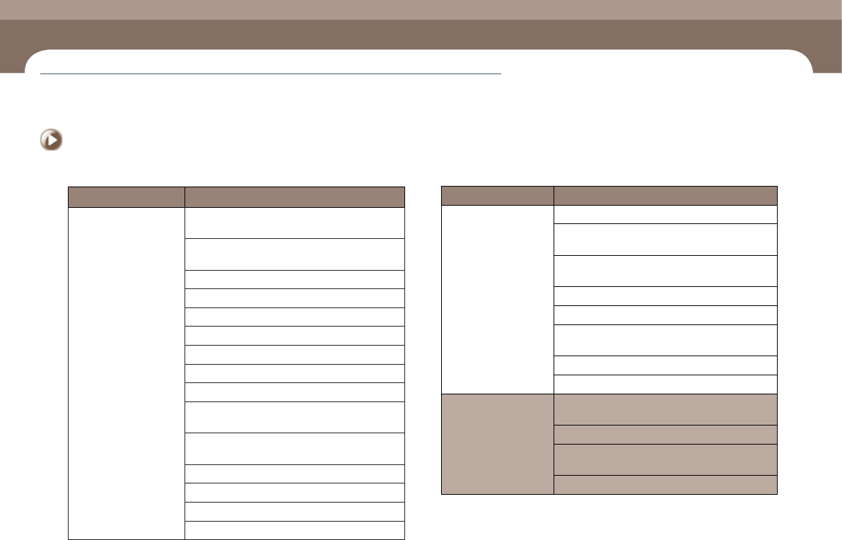
Classification of Causes Sub-classification of Causes
Pickup position Error
Incorrect XY coordinates of the pickup point due to
ball spline deformation
Incorrect setup of the XY coordinates of the pickup
point (Tape, Vibration, Tray Feeder)
Incorrect tape guide position
Splicing error
Incorrect Y position for pickup when installing tape
Incorrectly set X coordinate for pickup when installing tape
Incorrect pickup position adjustment
Incorrect feeder base adjustment
Part wear/distortion in the feeder
Sprocket, ratchet, etc., are contaminated with
foreign materials.
Incorrect setup of the part supply position according
to tray shape and part characteristics
Incorrect setup of Z and Pick Z values
Foreign materials in the feeder base slot and clamp
Incorrect Z offset setup
Z Offset change
◈Part recognition error
Classification of Causes Sub-classification of Causes
Failed to output the
images taken by the
camera
Defective fly camera or fix camera
Defective fly camera I/F cable or defective stage CAM
1 and 2 cables and connections
Defective Fly Camera PW Sync Exit Cable and
connection
Defective vision board
Defective vision I/F board
Defective camera I/O board (total destruction of
internal chips by fire)
Defective power supply
Defective vision board IF cable and connection
Damaged imagen from
the camera Unclear
image from the camera
Defective Fly Cam Sig Ext cable or Fix Cam signal
cable and connection
Defective camera focus
Contaminated camera lens and foreign material on
the lens
Camera dip switch setup error
Items to be inspected during production
Chapter 4
Next Generation, Multi-Functional Placer
DECAN S1 Operation Handbook
4-6
This chapter describes the methods for temporary stop of the
machine(Continue / Start mode), emergency stop (by manual/ by
system) and the restarting the production after emergency stop when
checking errors or other items and taking measures during production.
Take measures of instantaneous stop > Take measures against defective pickup
Take measures of instantaneous stop
Items to be inspected during production
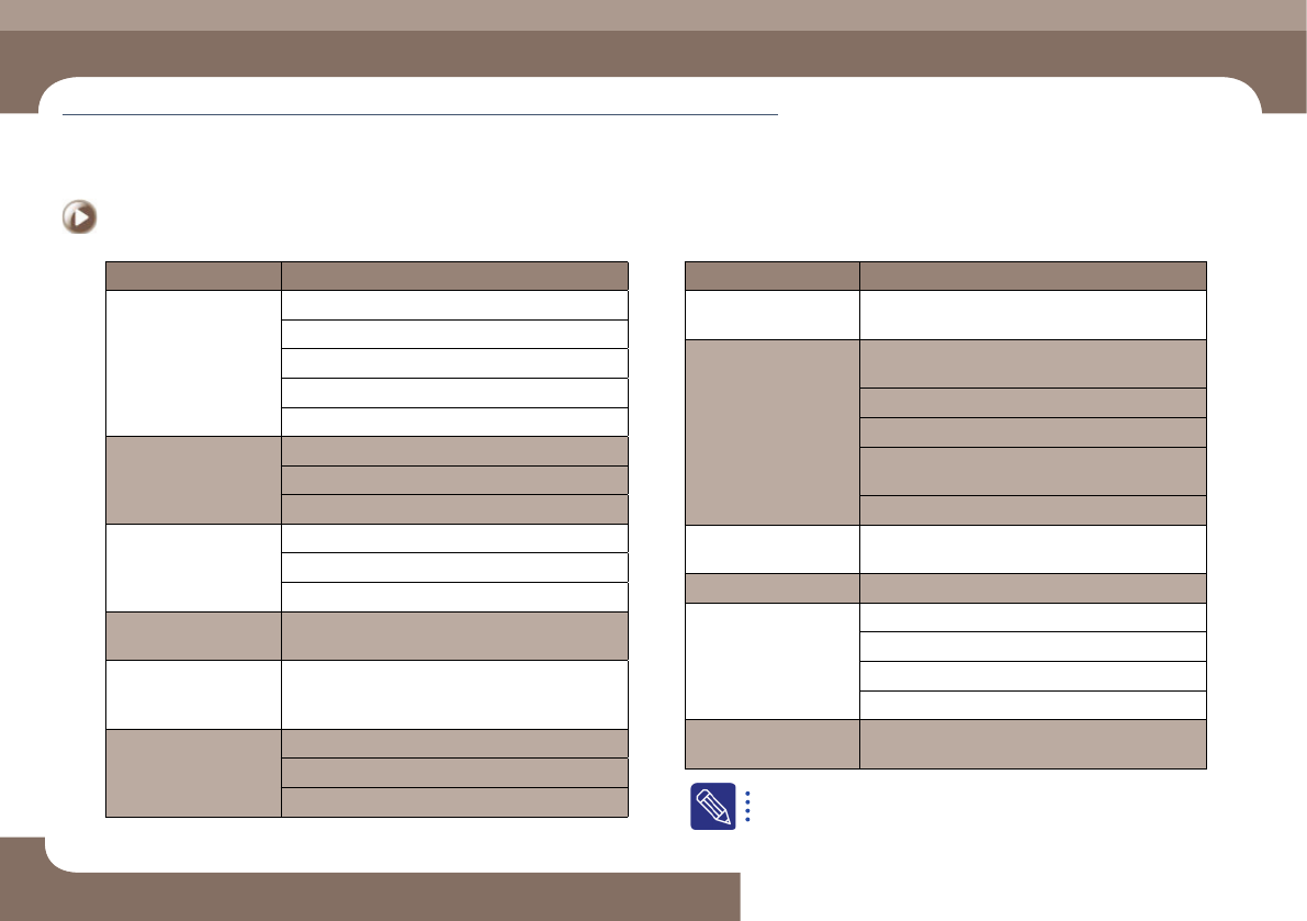
Classification of Causes Sub-classification of Causes
Vision processing timeout
/ Failed to recognize the
vision board
Defective Vision board connection
Defective SBC
Defective vision board
Defective backplane board
Damaged vision board driver file due to infection by virus
Damage to the mirror
Scratch to the mirror
Damaged mirror
Mirror contaminated with foreign material
Part data registration
error
Part recognition data registration error
Recognition parameter setup error
Illumination setup error
Defective part
The part size is different from that of the recognition
data of the registered part due to a defective part
Camera recognition
timeout error / Vision
processing timeout error
Defective vision board
Fiducial camera noise
(Occurrence of distorted
image, half image,
overlapped image, etc.)
Defective Vision board connection
Defective fiducial camera
Defective vision board I/F
Classification of Causes Sub-classification of Causes
Defective
cameraassembling
The camera recognition area is not located at the part
center but slightly offset in the X-axis or Y-axis direction
The image from the
camera is dark Abnormal
illumination brightness
Defective camera illumination board (Defective outer
illumination board)
Defective head illumination board
Defective fix camera illumination
The illumination LEDs turn on and off repeatedly due
to defective contact of the cable related to the lighting
Light mapping error
Foreign materials on the
cover glass
Contaminated nozzle
Defective side cylinder
Defective cable connection
Defective head I/O board
Abnormal sensor
Defective cylinder
Defective recognition of
'Ref' mark on the head
Contaminated 'Ref' mark on the head
For further details about the causes of defects and measures against
them, refer to '1.2.1. Pickup Error' in the Troubleshooting Guide.
Items to be inspected during production
Chapter 4
Next Generation, Multi-Functional Placer
DECAN S1 Operation Handbook
4-7
This chapter describes the methods for temporary stop of the
machine(Continue / Start mode), emergency stop (by manual/ by
system) and the restarting the production after emergency stop when
checking errors or other items and taking measures during production.
Take measures of instantaneous stop > Take measures against stuck tape vinyl
Take measures of instantaneous stop
2. Take measures against stuck tape vinyl
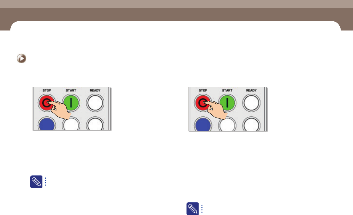
1. Stop the machine temporarily
Step 1.
Pressing the STOP button on the OP panel at the section where
the problem occurred will stop the machine temporarily.
Step 2.
Separate the tape feeder to which the problem occurred from
the feeder base and install the tape properly after eliminating
the cause of the problem. Then insert the tape feeder into the
feeder base and secure it and then start production again
Regarding tape installation, refer to 'Chapter2. Operation of the
Feeder' in the Feeder User Manual.
Step 3.
If the tape vinyl is stuck in the tape guide without being peeled
off properly, release the locker securing the tape guide and lift
it to examine the cause of the stuck tape.
Step 4.
In order to restart production, press the START button on the
corresponding OP panel.
3. Measures against PCB jamming
1. Manual emergency stop of the machine
Step 1.
If a PCB is jammed while moving between stations of the
conveyor, press STOP to stop the machine temporarily.
Step 2.
Open the door of the section to which the problem occurred
and press STOP and RESET and then solve the problem.
Step 3.
After solving the PCB jamming problem, select the station
indicated in red in the 'Conveyor Utilities' dialog box of the
MMI and click the <Delete> button.
Step 4.
Select the station in which the PCB is located currently and
click the <ReAcquire> button.
Regarding the method to restart the production after emergency stop
of the machine, refer to "2. Start mode: Restarts the production after
the occurrence of an error" (page 4-10)