DECAN_S1_Operation_EN.pdf - 第84页
Ch e ck o th e r s and r e plac e e xhaus t e d part s Chap ter 6 Nex t Generation, Multi- Funct ional Placer DE CAN S 1 Ope ra tio n Han db oo k 6-1 1 This Chapter describes the items for which care must be exercised wh…
Check others and replace exhausted parts
Chapter 6
Next Generation, Multi-Functional Placer
DECAN S1 Operation Handbook
6-10
This Chapter describes the items for which care must be exercised while
using thetape feeder as well as the method to take measures when
parts are exhausted.
Checking Feeder > Precautions that need to be taken when you check the reel information
Checking Feeder
Check others and replace exhausted parts
11. Precautions that need to be taken when you check
the reel information
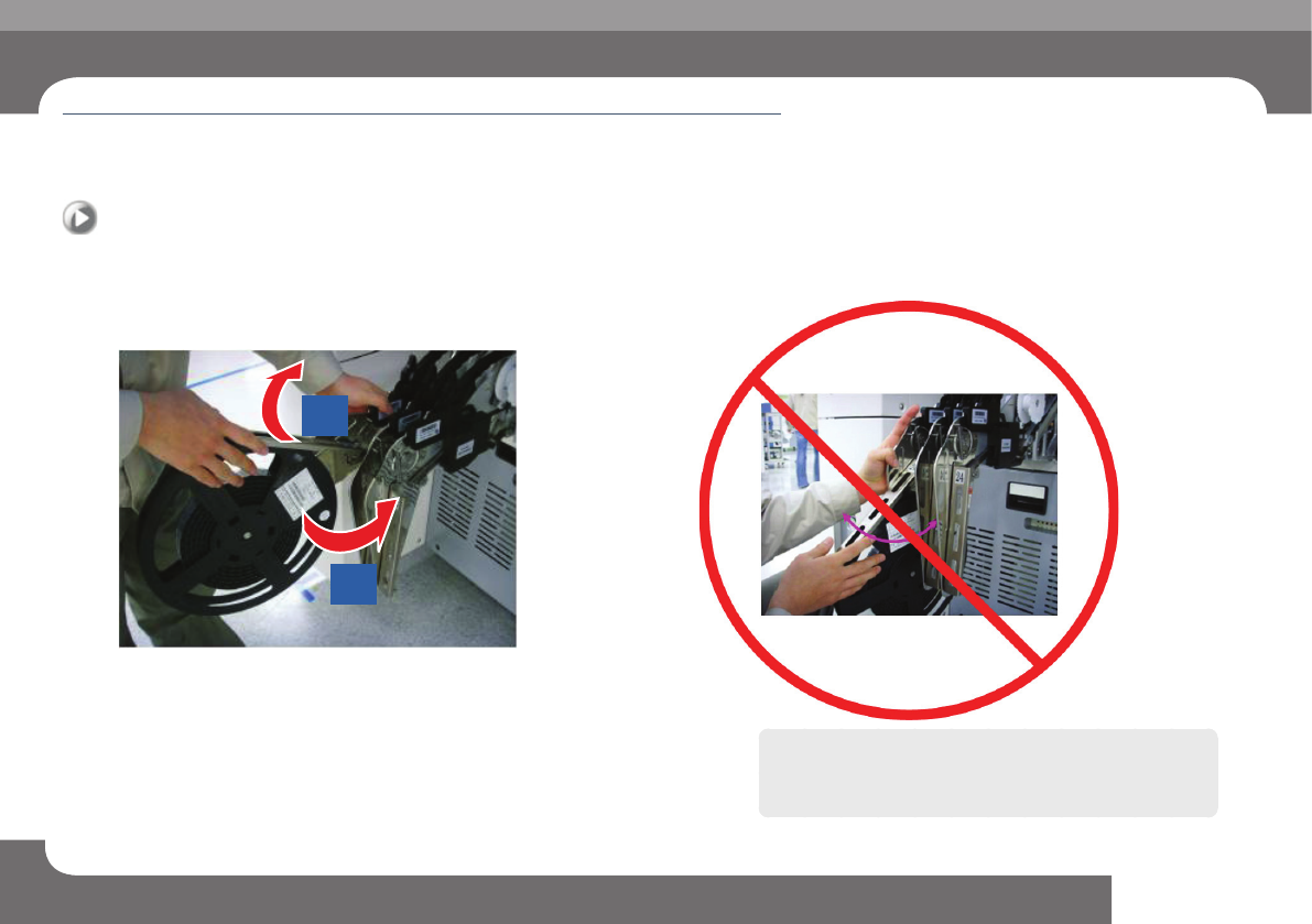
You should open the reel arm before you can check the reel information.
1
2
ㆍ When you check the reel information, you should open (lift) the reel arm plate
first.
Caution
If you try to move the reel arm plate sideways as shown in the
figure below, the reel arm plate may bend.
Check others and replace exhausted parts
Chapter 6
Next Generation, Multi-Functional Placer
DECAN S1 Operation Handbook
6-11
This Chapter describes the items for which care must be exercised while
using thetape feeder as well as the method to take measures when
parts are exhausted.
Arranging Backup Pins > Determining the positions of the backup pins
Arranging Backup Pins
1. Determining the positions of the backup pins
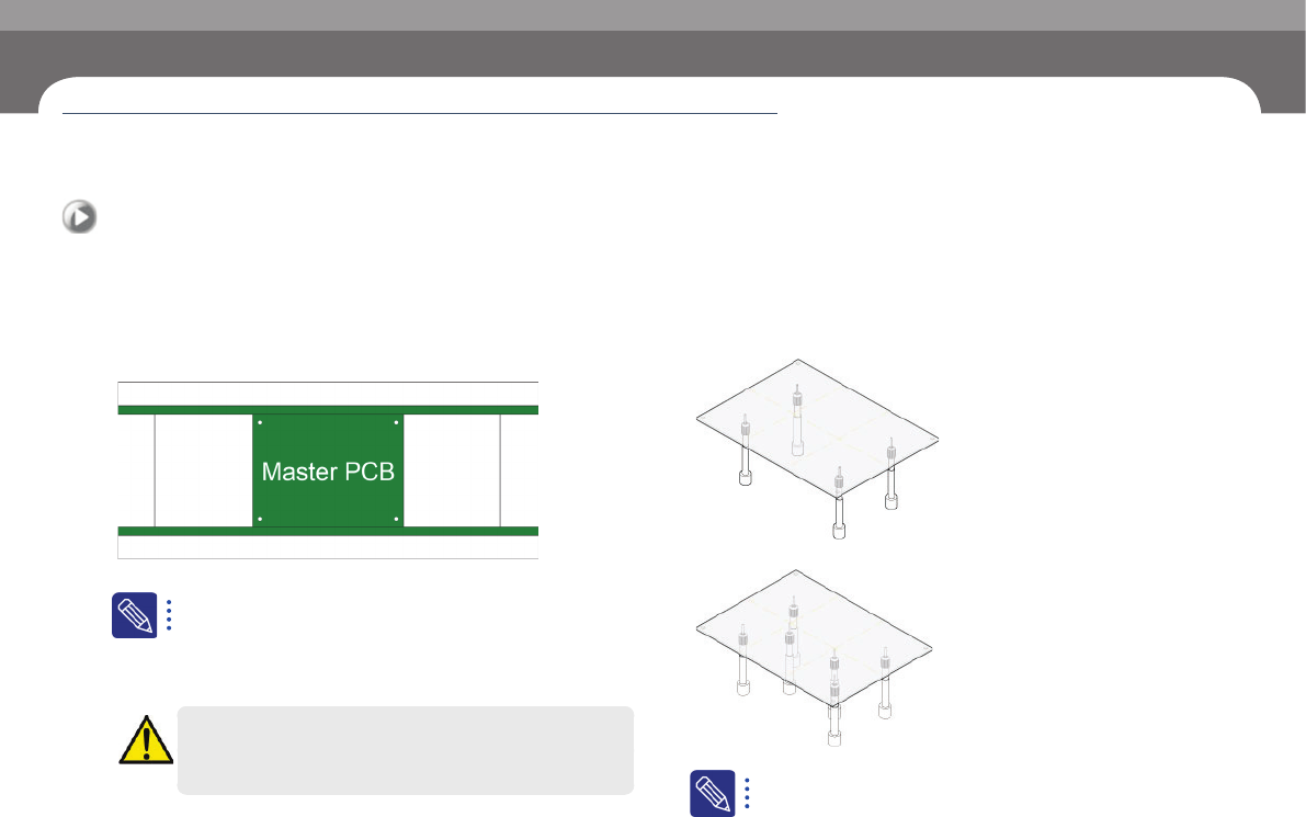
When you place the backup pins, you should avoid the hole
in the PCB.
Step 1.
Place the master PCB in the conveyer.
Manufacturing master PCB
ㆍ Master PCB prevents interference between backup pins and parts.
ㆍ For a double-faced PCB, a master PCB is manufactured which has
a hole in the bottom area where the parts are mounted.
Warning
Before removing the backup-pin, power off the motor.
Step 2.
Arrange backup pins.
① Place the backup pins on both sides where the PCB is bent the least.
② Place the backup pins where the parts are mounted in the central area .
The number of backup pins
ㆍ For a 200 mm-wide PCB, usually 6 backup pins are used.
Arranging Backup Pins
Check others and replace exhausted parts
Chapter 6
Next Generation, Multi-Functional Placer
DECAN S1 Operation Handbook
6-12
This Chapter describes the items for which care must be exercised while
using thetape feeder as well as the method to take measures when
parts are exhausted.
Arranging Backup Pins > Setting the height of backup pins
Arranging Backup Pins
Check others and replace exhausted parts
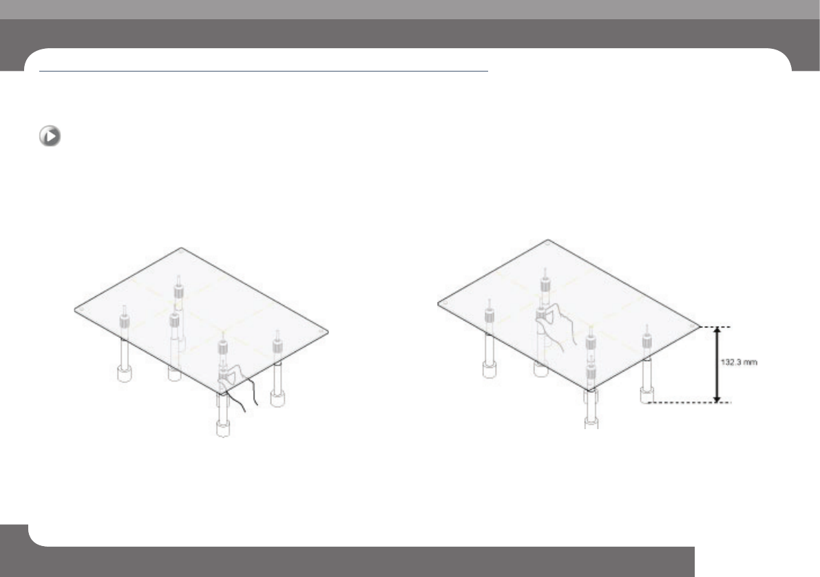
2. Setting the height of backup pins
You should set the height of backup pins after securing the
master PCB in the conveyer.(Height of backup pin: 132.3
mm in general)
Step 1.
Set the height of the backup pins in the sides.
Set the height so that the pins are in contact with the sides of the PCB.
Step 2.
Set the height of the backup pins in the central area.
Set the height of the central backup pins so that they are on the same level with
the pins on both sides.