DECAN_S1_Operation_EN.pdf - 第80页
Ch e ck o th e r s and r e plac e e xhaus t e d part s Chap ter 6 Nex t Generation, Multi- Funct ional Placer DE CAN S 1 Ope ra tio n Han db oo k 6 -7 This Chapter describes the items for which care must be exercised whi…
Check others and replace exhausted parts
Chapter 6
Next Generation, Multi-Functional Placer
DECAN S1 Operation Handbook
6-6
This Chapter describes the items for which care must be exercised while
using thetape feeder as well as the method to take measures when
parts are exhausted.
Checking Feeder > Tape Guide Vinyl Setting (Electrically Driven)
Checking Feeder
Check others and replace exhausted parts
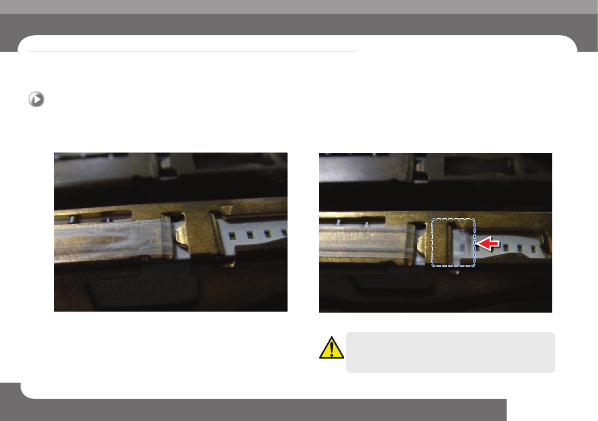
6. Tape Guide Vinyl Setting (Electrically Driven)
1. Install tape at the upper cover of the feeder
ㆍ Vinyl tape is installed normally
ㆍ Vinyl tape is curled
Caution
Exercise care so that the vinyl tape is not curled when setting the
tape at the front/rear slit
Check others and replace exhausted parts
Chapter 6
Next Generation, Multi-Functional Placer
DECAN S1 Operation Handbook
6-7
This Chapter describes the items for which care must be exercised while
using thetape feeder as well as the method to take measures when
parts are exhausted.
Checking Feeder > Tape Guide Vinyl Setting (Electrically Driven)
Checking Feeder
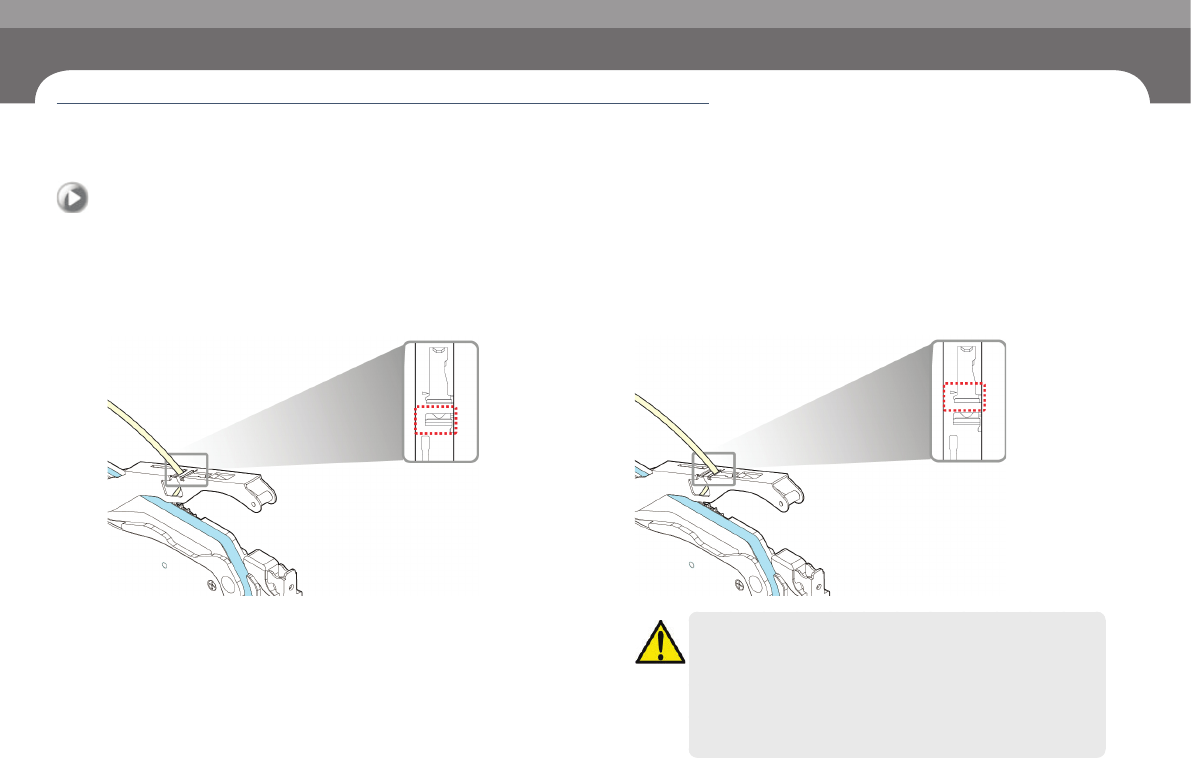
7. Tape Guide Vinyl Setting (Electrically Driven)
1. Install the tape through the front/rear slit
◈Install the tape through the rear slit(GENERAL)
◈Install the tape through the front slit(OPTION)
Caution
ㆍ In the case of 0402 parts, the tape must be installed in the
feeder through the front slit.
ㆍ When installing the tape for 0603 parts through the front slit,
use parts that are free of static electricity.
ㆍ If a part has static electricity, it may cause a pickup error due to
static electricity during its supply.
Check others and replace exhausted parts
Chapter 6
Next Generation, Multi-Functional Placer
DECAN S1 Operation Handbook
6-8
This Chapter describes the items for which care must be exercised while
using thetape feeder as well as the method to take measures when
parts are exhausted.
Checking Feeder > Checking if the feeder is properly mounted on the feeder base
Checking Feeder
Check others and replace exhausted parts
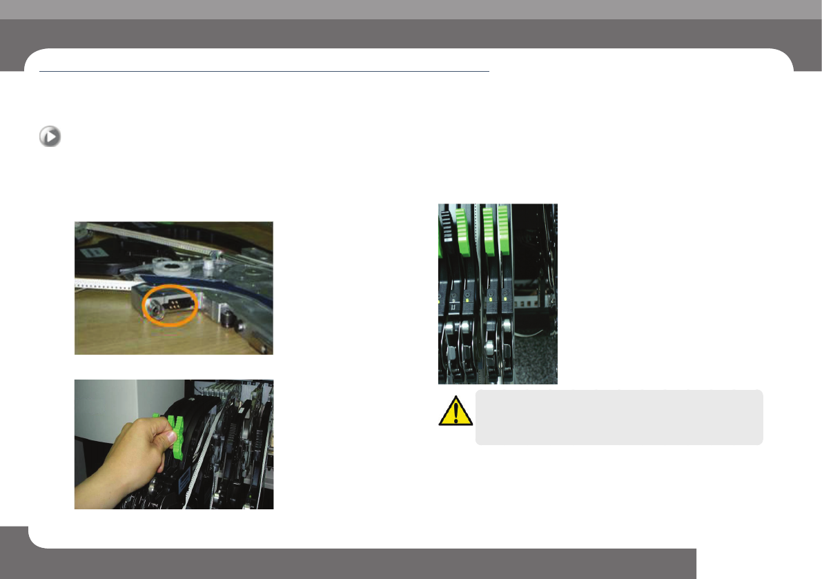
8. Checking if the feeder is properly mounted on the
feeder base
Step 1.
Check the probe pins of the feeder.
Step 2.
Secure the grip after mounting the feeder.
Step 3.
Check the LED color of the feeder.
Caution
When properly installed, the LED color is green. If the LED color is
not green even when the feeder is properly mounted, contact the
A/S center.