00900002-01_UM_ASM-ProcessLens_EN.pdf - 第47页
3 Machine description 3.1 Overview of the modules Instruction Guide ASM ProcessLens 02/2017 47 3.1.3 PCB conveyor assembly Fig.31: PCB Conveyor A Front side of the machine B Rear side of the machine 1 Rear conveyor rail…
3 Machine description
3.1 Overview of the modules
46 Instruction Guide ASM ProcessLens 02/2017
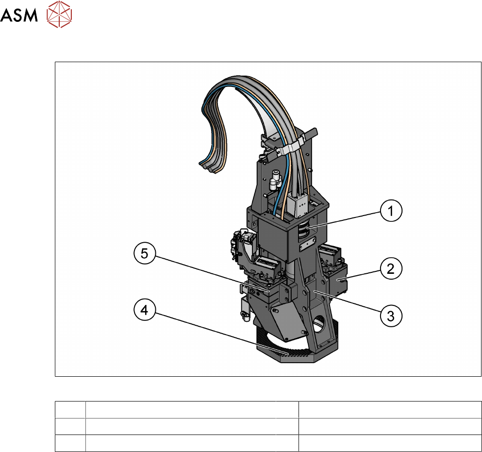
3.1.2 Inspection head
Fig.30: Inspection head
1 Imaging module (camera and lens mount) 2 Right source of 3D light
3 Top LED ring 4 Low LED ring
5 Left source of 3D light
3.1.2.1 Description
The optics head module, sitting on the gantry module, performs the image taking function, and
based on which, the expected inspection results are given.
The optics head module is split up into 2 parts, the DLP Projector Module and the Imaging Module.
The DLP projects fringes with different widths and frequencies onto the board, and the imaging
module grabs pictures and the system re-construct the 3D object based on those images taken.
3 Machine description
3.1 Overview of the modules
Instruction Guide ASM ProcessLens 02/2017 47
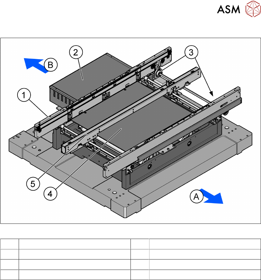
3.1.3 PCB conveyor assembly
Fig.31: PCB Conveyor
A Front side of the machine B Rear side of the machine
1 Rear conveyor rail 2 Conveyor control unit
3 Fixed front rail 4 Lifting table
5 Stopper and sensors rail
3.1.3.1 Description
The PCB conveyor is a single lane conveyor. The machine requires a length of 1100 mm. Both
sides have a 15 mm extension to the upstream or downstream conveyor. The total length of the
conveyor is 1130 mm. The standard conveyor is a front fixed rail and it only has one lifting table
without input/output buffer. A conveyor extension option exists to increase the length of the single
stage conveyor to allow for a barcode capability to be attached where no upstream conveyor ex-
ists.
3 Machine description
3.1 Overview of the modules
48 Instruction Guide ASM ProcessLens 02/2017
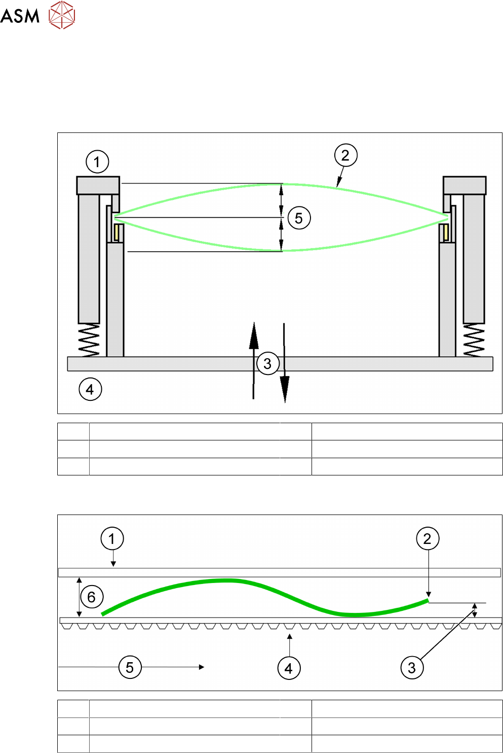
3.1.4 Definition of PCB warpage
This is the maximum allowable PCB warpage for the SPI to be able to measure accurately.
3.1.4.1 PCB warpage on the conveyor
PCB warpage across the direction of travel max. 1% of the PCB diagonal, but not exceeding
±5mm.
1 Fixed clamped edge 2 Printed circuit board
3 Movable clamping device 4 Conveyor rail
5 +/- 4.5 mm
PCB warpage in the direction of transport + PCB thickness < 5.5 mm. Bending up of board edge
max. 2.5 mm.
1 Fixed clamped edge 2 Front board edge
3 Max. 2.5 mm 4 Conveyor belt
5 PCB transport direction 6 5.5 mm