00900002-01_UM_ASM-ProcessLens_EN.pdf - 第65页
4 Setting up and commissioning 4.3 Setting up the machine Instruction Guide ASM ProcessLens 02/2017 65 4.3.6 Levelling the machine ► Level the machine in the X and Y direction with the help of the machine spirit level. F…
4 Setting up and commissioning
4.3 Setting up the machine
64 Instruction Guide ASM ProcessLens 02/2017
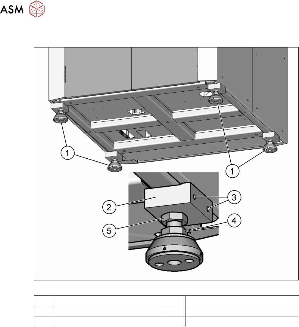
4.3.5.1 Presetting the height of the machine feet
The machine stands on 4 feet.
Fig.39: Presetting the height of the machine feet
1 Machine feet 2 Block for package and support
3 M10 x 20 for packaging 4 M24 x M36 nut
5 M24 x M36 nut
► Measure the approximate PCB conveyor height.
► Lift the ASM ProcessLens machine with a forklift.
► Loosen the two clamping nuts (4 and 5) with help of open end spanner size 36mm.
► Turn the ASM ProcessLens machine feet (1) with the bottom screw nut (4) so that the
machine reaches the desired PCB conveyor height.
► Repeat for the other three feet.
► Now use the forklift to carefully lower the machine until the machine feet touch the floor
evenly. There should always be a second person present to ensure that the machine remains
stable while it is being lowered.
See also
2 4.3.5.1 "Presetting the height of the machine feet" [}64]
4 Setting up and commissioning
4.3 Setting up the machine
Instruction Guide ASM ProcessLens 02/2017 65
4.3.6 Levelling the machine
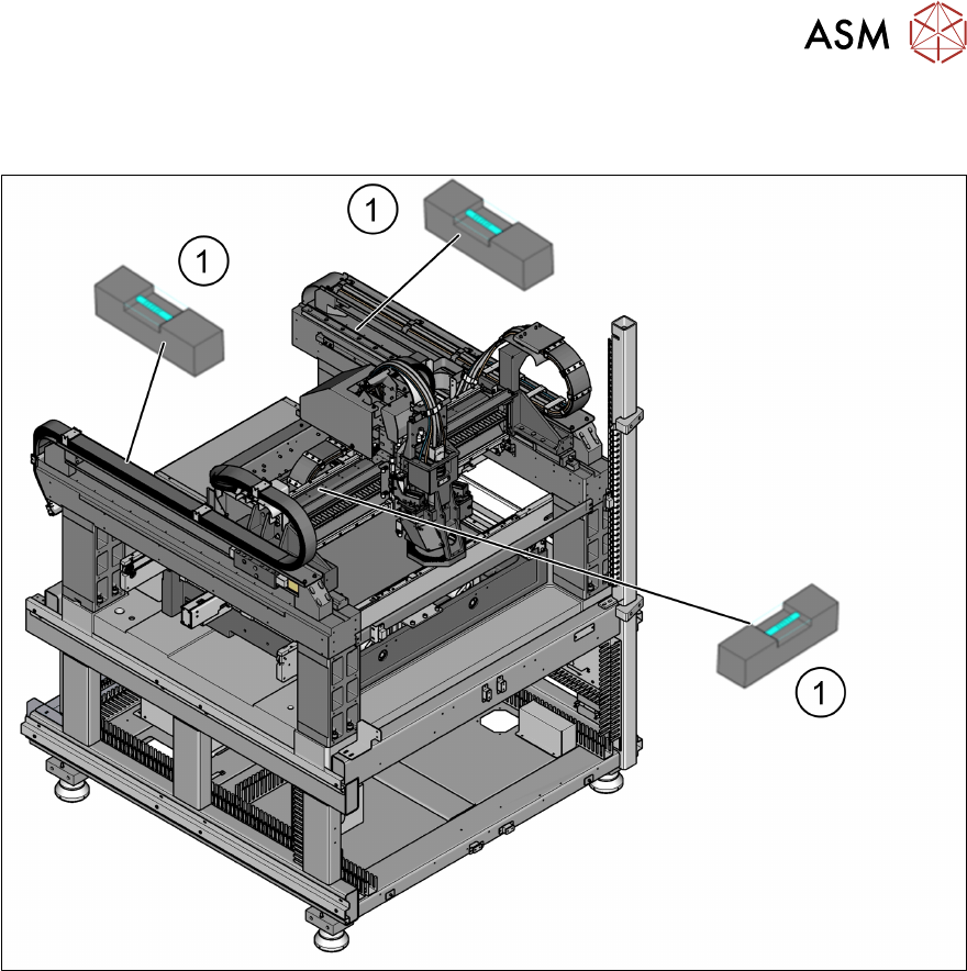
► Level the machine in the X and Y direction with the help of the machine spirit level.
Fig.40: Position of the machine spirit level in the X and Y direction
► Place the machine spirit levels (1) in the X and then the Y direction on the linear guide rails.
► Measure the distance between the upper edge of the PCB conveyor belt and the floor. This
distance should be the range from to 950 mm, if the height of the machine is to be set to
950mm. Other heights also apply.
► Turn the bottom screw nut (item 4 in fig. "Presetting the height of the machine feet" [}64]) of
all four machine feet, so that the fluid in the machine spirit level does not deviate from its zero
point (tolerance within ±0.05mm) at the required conveyor height.
► Check the required board conveyor height.
► Once the machine has been levelled, tighten the top secure nut (item 3 in fig. "Presetting the
height of the machine feet" [}64]) to clamp all machine feet.
► Use the spirit level to check that the machine is precisely levelled (tolerance within
±0.05mm).
See also
2 4.3.5.1 "Presetting the height of the machine feet" [}64]
4 Setting up and commissioning
4.4 Commissioning the machine
66 Instruction Guide ASM ProcessLens 02/2017
4.3.7 Removing the corrosion protection from the guide rails
The machines were given a corrosion protection treatment before they were delivered. Wipe off
from all the axes and bearings with a lint-free cloth.
CAUTION
Corrosion protection
► You should therefore remove the corrosion protection from all the axes and bearings
when you traverse the machine axes for the first time during commissioning.
► Grease all the axes and bearings with the grease described in the maintenance
instructions.
If the corrosion protection agent is mixed with the bearing grease on the axes this can greatly re-
duce the service life of the bearings and guide rails.
CAUTION
Cleaning the guide rails
Do not allow any alcohol to enter the guide carriages when you clean the guide rails and
scale rods. Alcohol will damage the bearing grease in the guide carriages.
4.4 Commissioning the machine
4.4.1 Commissioning the machine at the installation site
► Check all modules for correct seating.
► Store the machine until room temperature has been reached (minimum 4 hours). There is oth-
erwise a risk of condensation occurring.
ð Open all covers and doors.
ð Open the front lower cover plate.
ð Open the upper and lower rear cover.
ð Remove the desiccation bag.
► Wipe off the linear guide rails with a lint-free cloth before removing the shipping braces.
CAUTION
Do not use any solvents
► Please see section 4.3.7 "Removing the corrosion protection from the guide
rails" [}66].