00900002-01_UM_ASM-ProcessLens_EN.pdf - 第57页
4 Setting up and commissioning 4.1 Transport and delivery configuration Instruction Guide ASM ProcessLens 02/2017 57 Fig.35: Contact surfaces - forks parallel to the direction of PCB transport 1 Contact surface for fork…
4 Setting up and commissioning
4.1 Transport and delivery configuration
56 Instruction Guide ASM ProcessLens 02/2017
4.1.5 Transporting the machine without a crate or pallet
4.1.5.1 Safety instructions
WARNING
Risk of injury
► The applicable accident prevention regulations concerning the transportation of heavy
goods must be followed.
► In particular, you should wear safety boots to minimize the risk of crushing your feet.
► Read this section in full before transporting the machine to avoid severe damage.
► When you are transporting the machine, make sure that all the feet are clear of the
floor. If they are not clear, the feet will drag along the floor and bump into obstacles.
This could damage the machine foot thread in the machine frame.
4.1.5.2 Means of transport
Use a forklift truck with the following specification to carry the machine:
Fork length min. 1800 mm
Lifting power min. 6000 kg
Distance between forks with the forks running parallel
to the direction of PCB transport.
Approx. 420 mm
4.1.5.3 Forklift attachment points on the machine
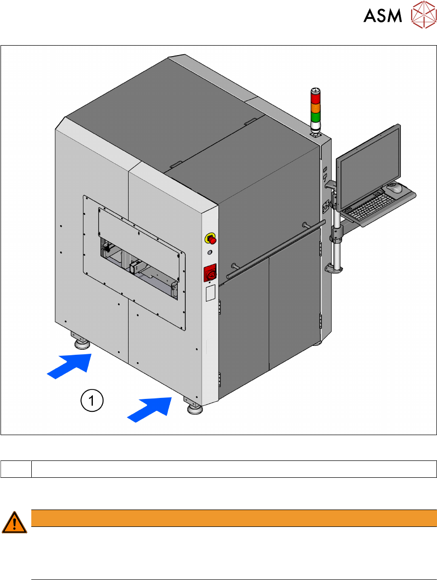
The diagram in 4.1.5.3 "Forklift attachment points on the machine" [}56] shows the forklift attach-
ment points on the machine for lifting the machine off the pallet or transporting it without the pallet.
WARNING
Risk of injury
► Always use a pallet and forklift to transport the machine over longer distances in order
to avoid damaging the machine.
WARNING
Risk of injury
Please note the following points before you raise the machine in order to avoid irreversible
damage to the machine.
► The forks must be aligned parallel to the PCB conveyor.
► Make sure to push the forks all the way through. Not pinching cables. There is an area
in the center of the machine's base plate where there is a fan. If the forks are not go-
ing through fully, they could lift up the machine and be in contact with the fan and not
the machine's base plate which means the fan would get destroyed.
► The forks may only be opened to a degree which ensures that they are still within the
contact area of the machine underside (see 4.1.5.3 "Forklift attachment points on the
machine" [}56]).
► Do not increase the distance between the forks so that the machine is lifted outside
this contact surface. This would lead to deformation of the machine frame and/or dam-
age to the cables and leads.
► Make sure that the forks are evenly loaded when you lift the machine.
► A firm support between the forks and machine will prevent the machine tilting when it
is raised. This will also prevent a one-sided load on the machine feet, which would de-
form the fixing of the machine feet. We recommend that a second person watch the
machine as it is raised, and make sure that the machine does not tip to one side when
lifted with the forklift.
4 Setting up and commissioning
4.1 Transport and delivery configuration
Instruction Guide ASM ProcessLens 02/2017 57
Fig.35: Contact surfaces - forks parallel to the direction of PCB transport
1 Contact surface for forklift truck forks
4.1.5.4 Points that MUST be noted when transporting the machine
WARNING
Risk of injury
► When you are transporting the machine, make sure that all the feet are clear of the
floor. If they are not clear, the feet will drag along the floor or bump into obstacles.
This could damage the machine feet and/or the foot fixtures.
4 Setting up and commissioning
4.2 Infrastructure at the installation location
58 Instruction Guide ASM ProcessLens 02/2017
4.2 Infrastructure at the installation location
4.2.1 Recommendations for foundation quality
The foundation on which the machine is installed must be firm and levelled, as dynamic forces
could cause vibrations when the machine is operated. The degree of vibration depends on the con-
struction of the foundation. The following are suitable provided that the floor loading parameters,
etc., are not exceeded:
●
Reinforced concrete ceiling constructions, e.g. ceilings in production halls
●
Reinforced concrete floor slabs, e.g. concrete floors in production halls without a basement
●
Rooms with double floors, provided that a stable foundation is included in the space between
them. The same setup conditions apply to this intermediate foundation, which can be made
from steel girders or concrete.
4.2.1.1 Maximum ground levelness
The floor underneath the machine may not exceed an incline of 0.63%. This corresponds to an in-
cline of 5mm over a distance of 800 mm.
4.2.1.2 Machine weight and floor loading
The machine weight and floor loading values can be found in section 3.2.1 "Dimensions and Setup
Conditions" [}51].
4.2.2 Main power supply
WARNING
Some parts of the system carry potentially lethal voltages
The machine is supplied with 1/N/PE 110 V~ to 240 V~, 50/60 Hz mains voltage. This
means that some parts of the system carry potentially lethal voltages - even when switched
off at the main power switch. Incorrect handling of the machine can therefore result in death
or severe injury or considerable damage to equipment.
► Always follow the applicable accident prevention and safety regulations (particularly
DIN EN 60204, part 1 or IEC 60204, part 1) and the safety regulations in your own
country.
4.2.2.1 Checking the main power supply
Check whether the power supply complies with the prescribed machine specifications (see table in
section 3.2.3 "Electrical Ratings" [}52]).
NOTICE
Load peaks occur in the power supply
For technical reasons, load peaks occur in the power supply. Please contact your power
company to clarify the mains impedance, if necessary.
4.2.2.2 Power supply cable - specification
The following specifications apply at the customer end to the power supply for the machine:
●
3 x 2.5 mm² (1 x 240 V~) at cable lengths of up to 20 meters between ASM ProcessLens dis-
tribution and mains connection at the customer end. Over 20 meters cable 3 x 4 mm².
The color coding for the wires will depend on the country in which the system is operated.
WARNING
Electrical leads must be clearly labelled
The electrical leads to each individual machine and to the options installed must be clearly
labelled and easily assignable. The regulations of the country in which the machine is oper-
ated apply.