00900002-01_UM_ASM-ProcessLens_EN.pdf - 第73页
5 Working with the machine 5.1 Controls and displays Instruction Guide ASM ProcessLens 02/2017 73 5.1.2 Description All the controls can be reached by a 1.40 m tall person. Programmable tower lamp with buzzer (see fig. &…
5 Working with the machine
5.1 Controls and displays
72 Instruction Guide ASM ProcessLens 02/2017
5.1 Controls and displays
5.1.1 Overview
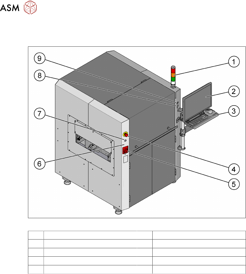
Fig.44: Controls and displays
1 Tower lamp with buzzer 2 LCD monitor
3 Keyboard and mouse 4 EMERGENCY STOP button
5 Main switch 6 Machine idle lamp
7 Key switch 8 Start button (green)
9 Stop button (black)
5 Working with the machine
5.1 Controls and displays
Instruction Guide ASM ProcessLens 02/2017 73
5.1.2 Description
All the controls can be reached by a 1.40 m tall person.
Programmable tower lamp with buzzer
(see fig. "Controls and displays" [}72])
The programmable tower lamp is used to signal operating statuses and malfunctions of the
machine. The buzzer indicates when an alert has occurred. The sequence of colors of the tower
lamps is red - amber - green.
The programmable tower lamp functionality allows the operator to assign a combination of the fol-
lowing tower lamps conditions to machine events:
Condition Possible states Frequency of flashes
Green On
Off
Pulse
Pulse Frequency (ms)
Amber On
Off
Pulse
Pulse Frequency (ms)
Red On
Off
Pulse
Pulse Frequency (ms)
Buzzer On
Off
Pulse Frequency (ms)
LCD monitor
(see fig. "Controls and displays" [}72])
There is a flat LCD monitor at the front side of the ASM ProcessLens machine. A LCD monitor with
a touch-sensitive surface (touchscreen) as an option is available.
Keyboard
(see fig. "Controls and displays" [}72])
The keyboard and mouse are located beneath the monitor.
CAUTION
Risk of collision of personnel with monitor and keyboard holder
Risk of collision of the front hood with the arm where the monitor, keyboard and mouse are
mounted.
Key switch ON/OFF
(see fig. "Controls and displays" [}72])
Turn on the control power manually and switch the conveyor into pass through mode when the PC
is down.
► Close the GUI program.
► Switch off the machine by the main switch.
► Wait for 30 sec and then switch on the machine at the main switch.
► Turn the key switch to the left and release to turn on the control power.
► Turn the key switch to the right.
The conveyor set to pass through running mode.
Main power switch in ON position
(see fig. "Controls and displays" [}72])
After switching on the main power switch, 24 V DC and 240 V AC are present.

5 Working with the machine
5.1 Controls and displays
74 Instruction Guide ASM ProcessLens 02/2017
Main power switch in OFF position
(see fig. "Controls and displays" [}72])
The main power switch disconnects the single phase from the power supply.
DANGER
Death, serious injury or considerable damage may result if these machines are
handled incorrectly
► Always follow the applicable accident prevention and safety regulations (particularly
DIN EN 60204, part 1 or IEC 60204, part 1) and the safety regulations in your own
country.
► The safety door to the power supply must ONLY be opened by appropriately qualified
and trained personnel.
Machine idle lamp
(see fig. "Controls and displays" [}72])
On: The main power switch is switched to ON position. Power is supplied to the power distribution
module.
Off: The input voltage is not present.
Start button, green
(see fig. "Controls and displays" [}72])
After switching on the main power switch and having started the inspection software press the start
button to set ASM ProcessLens into regular inspection mode. Do the same if the EMERGENCY
STOP had been engaged and is now released or if the protective hood had been opened and is
now closed.
Stop button, black
(see fig. "Controls and displays" [}72])
This button is used to stop the machine and will perform the following tasks:
●
Stop the production operations and puts the machine in idle mode.
●
The control power is still present.
The EMERGENCY STOP button is red and latches in the ON position when pressed. When you
press the EMERGENCY STOP button, the switching contact of safety interlock module opens.
The signaling contact of the EMERGENCY STOP button opens.
The inspection cycle is interrupted and can then either be continued or cancelled once the machine
is working correctly again.
NOTICE
ASM ProcessLens electrical diagrams
For details, please refer to the ASM ProcessLens electrical diagrams.
Release the EMERGENCY STOP button
●
Release the EMERGENCY STOP button from latched position after being activated.
●
Operator can press the START button, to resume production operation.
●
The software sequence for START button as follows:
– Software will check that the hood is closed and EMS is not activated.
– Software will lock the door and reset the safety relay.
– Software will check that the safety relay interlock is cleared and enable the motors.
See also
2 5.1.1 "Overview" [}72]