XP Type II 工程师培训手册 (2.0).pdf.pdf - 第197页
FK-9F98-34 XP Series T ype II T raining T ext for Service Engineers Edition 2.0 XP242E – Chapter 8 T ype II MTU Adjustment Page 4 of 18 2. Adjust the position of the shuttle rails so that they are aligned with the refere…
FK-9F98-34 XP Series Type II Training Text for Service Engineers
Edition 2.0 XP242E – Chapter 8 Type II MTU Adjustment Page 3 of 18
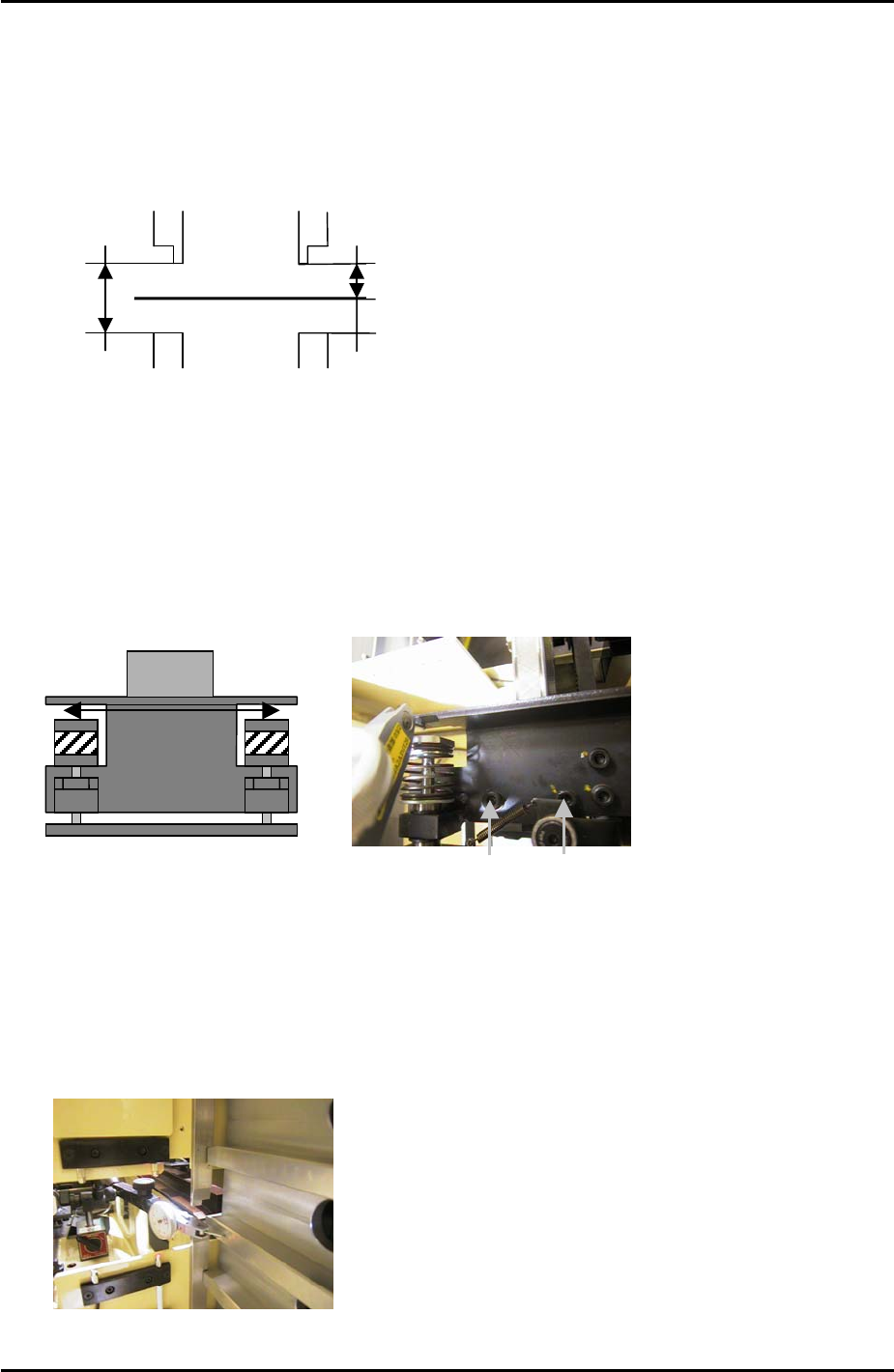
8.5 Guide Rail Adjustment
1. Place an empty tray pallet in slot [01,02] and bring it to the “T_TrayOrg” position.
2. Adjust the upper guide rails so that they are 9mm above the tray pallet surface.
3. Adjust the lower guide rails so that they are 19mm beneath the upper guide rails.
Tray Pallet
9mm
19mm
8.6 U Axis Clamper Parallelism Check and Adjustment
1. Use an extension bar to attach a dial gage to the placing head and adjust the parallelism
of the U axis shuttle so that it is parallel to the X-axis. Tolerance is 0.03mm. Refer to the
diagram and photo below:
To adjust the parallelism loosen these
two bolts
MC Front
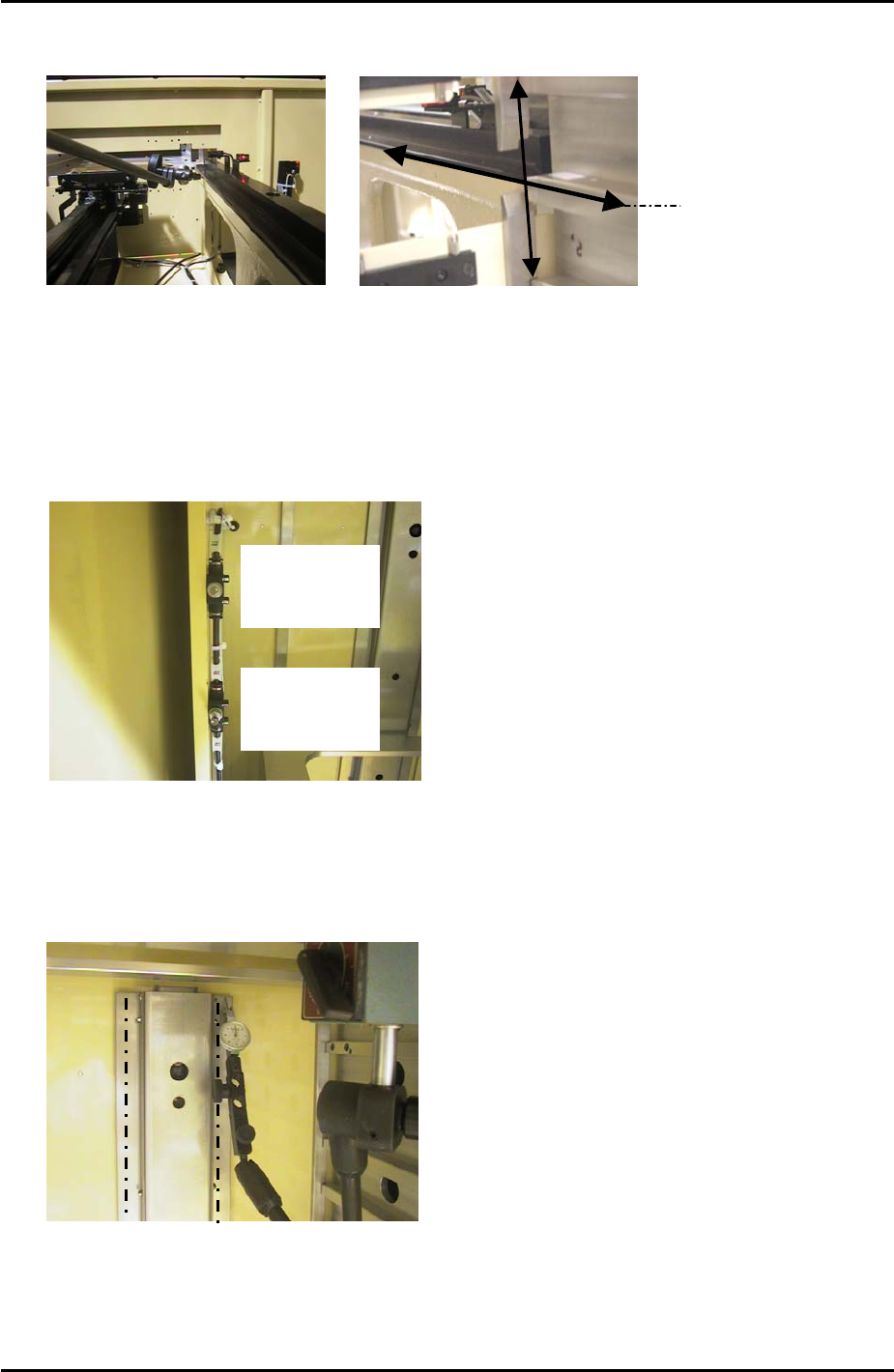
8.7 Shuttle Rail Position Adjustment
1. Use a dial gage to measure the width of all the slots. Find the average slot to use as a
reference, refer to the photo below:
Use a dial gage to measure the width
of all the slots, and use the slot with
an average width as the reference.
Fuji Machine Mfg. Co., Ltd. Okazaki
SMT Equipment Quality Assurance Dept.
8 – 3 CS Section
FK-9F98-34 XP Series Type II Training Text for Service Engineers
Edition 2.0 XP242E – Chapter 8 Type II MTU Adjustment Page 4 of 18
2. Adjust the position of the shuttle rails so that they are aligned with the reference slot,
tolerance is 0.05mm.
Measure along this line
3. Be careful when measuring the alignment as the first few centimeters of the shuttle rails
are tapered. Measure at the point where the shuttle rail is straight.
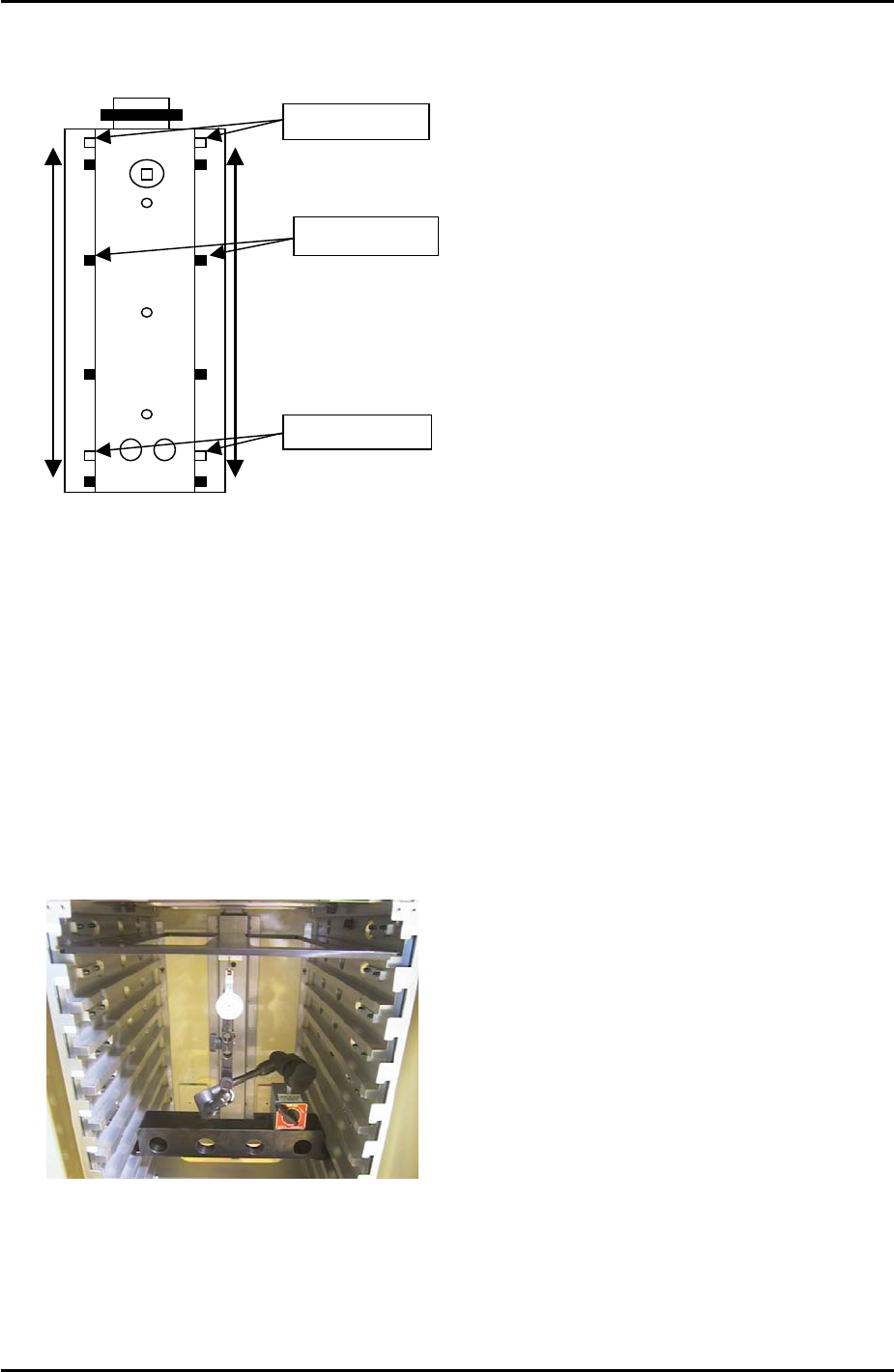
8.8 Tray Pusher Adjustment 1
1. Set the speed controllers for the tray pusher as follows:
Bwd: 5 turns
from fully
closed
Fwd: ¾ turn
from fully
closed
2. Turn I/O Y033: TrayPusherBwd OFF, and I/O Y032 TrayPusherFwd ON to bring the
pusher to its forward position.
3. Attach a dial gage stand to the magazine and set the dial gage tip on the pusher as
shown below:
4. Measure the flatness of the left and right hand pusher panels. Measure from top to
bottom as illustrated by the dotted lines in the photo above.
5. If necessary loosen the installation bolts on the panels, and adjust the flatness with the
Fuji Machine Mfg. Co., Ltd. Okazaki
SMT Equipment Quality Assurance Dept.
8 – 4 CS Section
FK-9F98-34 XP Series Type II Training Text for Service Engineers
Edition 2.0 XP242E – Chapter 8 Type II MTU Adjustment Page 5 of 18
eccentric pin. Adjust so that the dial gage reads 0 at the top of the pusher and 0 at the
bottom. Also measure the points in between, tolerance is +/-0.15mm
Fixing Bolts
Eccentric Pin
Fulcrum Pin
8.9 Tray Pusher Adjustment 2
1. Reverse the I/Os set in the previous adjustment. Turn Y032 TrayPusherFwd OFF, and
Y033: TrayPusherBwd ON.
2. Set the T axis 3mm below the + limit.
3. Set the tray pallet jig (Z9631DEPJ3740) in the magazine top slot, and set a magnet on
the underside. Confirm that the tray pallet jig is in contact with the guide bar.
4. Set the large block jig (Z9631ADEPJ8172) in slot [41,42].
5. Set the dial stand on the block jig and the dial gage to 0 on the magnet as shown below:
6. Descend the T-axis and watch the dial gage to find the position where the guide bar is
most forward.
7. Bring the T-axis back to 3mm below the + limit and set the tray pallet jig in the slot that is
in the position where the guide bar is most forward.
Fuji Machine Mfg. Co., Ltd. Okazaki
SMT Equipment Quality Assurance Dept.
8 – 5 CS Section