XP Type II 工程师培训手册 (2.0).pdf.pdf - 第203页
FK-9F98-34 XP Series T ype II T raining T ext for Service Engineers Edition 2.0 XP242E – Chapter 8 T ype II MTU Adjustment Page 10 of 18 8.14 T ray Height Check Sensor & [T_T rayEmptyOrg] Measurement 1. Put the tray …
FK-9F98-34 XP Series Type II Training Text for Service Engineers
Edition 2.0 XP242E – Chapter 8 Type II MTU Adjustment Page 9 of 18
8.12 Tray Catch Original Position Check Sensor Adjustment
1. Jog the U axis to the [U_ShuttleClampPos] + 3.43mm.
2. Loosen the sensor bracket and find the position that the sensor just comes ON, then lock
the sensor a further 0.5mm in the ON direction.
“TrayCatchOrgPo” Sensor
3. Confirm the sensor operation with I/O: X030 TrayCatchOrgPo.
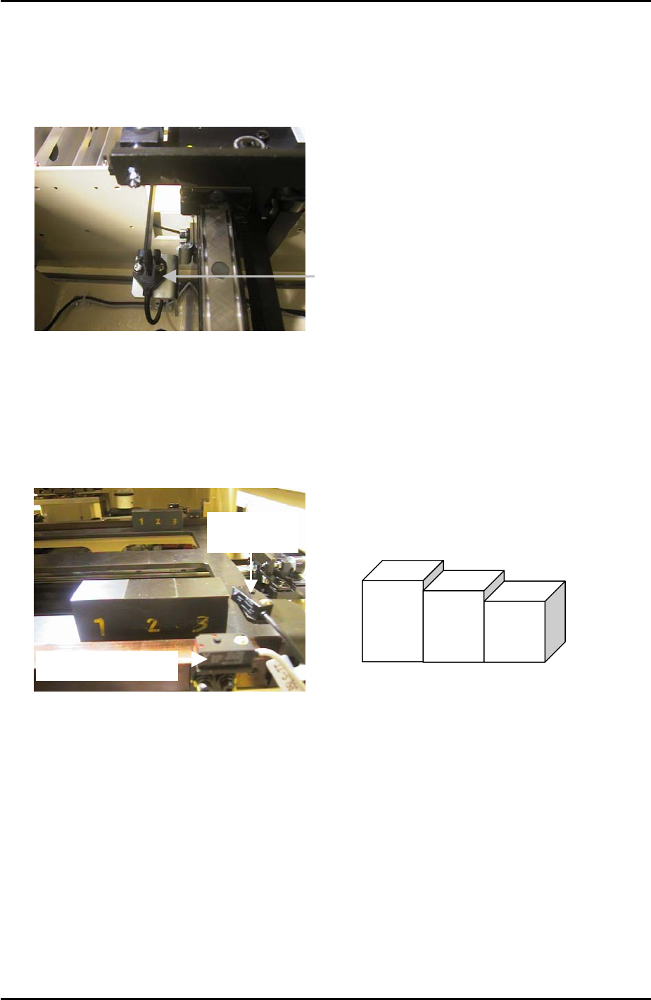
8.13 U-axis Interlock Sensor Adjustment
1. Put the tray pallet jig and two of the “three step jigs” in the U axis as shown below:
Interlock Sensor
Tray Height
check Sensor
“Three step jig” Z9631DEPJ3750
3
2
1
2. Adjust the height of the interlock sensor receiver and transmitter so that “X033
UaxisInter” is OFF when step 1 of the jig is in line with the sensor, and ON
when step 3 of
the jig is in line with the sensor.
Fuji Machine Mfg. Co., Ltd. Okazaki
SMT Equipment Quality Assurance Dept.
8 – 9 CS Section
FK-9F98-34 XP Series Type II Training Text for Service Engineers
Edition 2.0 XP242E – Chapter 8 Type II MTU Adjustment Page 10 of 18
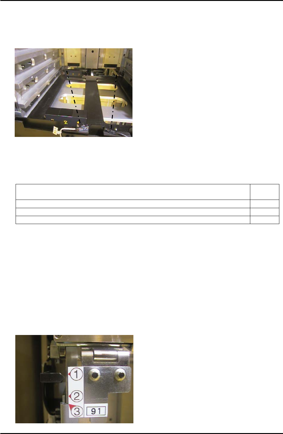
8.14 Tray Height Check Sensor & [T_TrayEmptyOrg] Measurement
1. Put the tray pallet jig in slot [01,02] and bring it to the [T_TrayOrg] position.
2. Place two of the “three step” jigs on the tray pallet jig as shown below:
3. The path of the sensor beam is illustrated by the dotted line in the photo above.
4. Adjust the height of the “X03A TrayHeightChk1” sensor transmitter and receiver as
follows:
Jig Combination I/O
Status
Step 2 + 2 of the step jigs are in line with the sensor transmitter and receiver ON
Step 2 + 3 of the step jigs are in line with the sensor transmitter and receiver ON
Step 3 + 3 of the step jigs are in line with the sensor transmitter and receiver OFF
5. Repeat the adjustment for the “X03B TrayHeightChk2” sensor transmitter and receiver.
6. Remove the two “three step” jigs from the MTU, leaving only the tray pallet jig.
7. Slowly jog the T-axis up until both “X03A TrayHeightChk1” and “X03B TrayHeightChk2”
come ON. This position is “T_TrayEmptyOrg”. Select [Maintenance C] – [Proper Data
Editor] – [T_TrayEmptyOrg] – [Direct Servo Input] to save the current counter value in
proper data.
8.15 Tray Shutter Check Sensor Adjustment
1. Adjust the position of the sensor bracket so that when the tray shutter is at position 1 the
sensor LED is OFF, and comes ON when raising the shutter by 1mm.
X032 TrayShutOpnChk
Fuji Machine Mfg. Co., Ltd. Okazaki
SMT Equipment Quality Assurance Dept.
8 – 10 CS Section
FK-9F98-34 XP Series Type II Training Text for Service Engineers
Edition 2.0 XP242E – Chapter 8 Type II MTU Adjustment Page 11 of 18
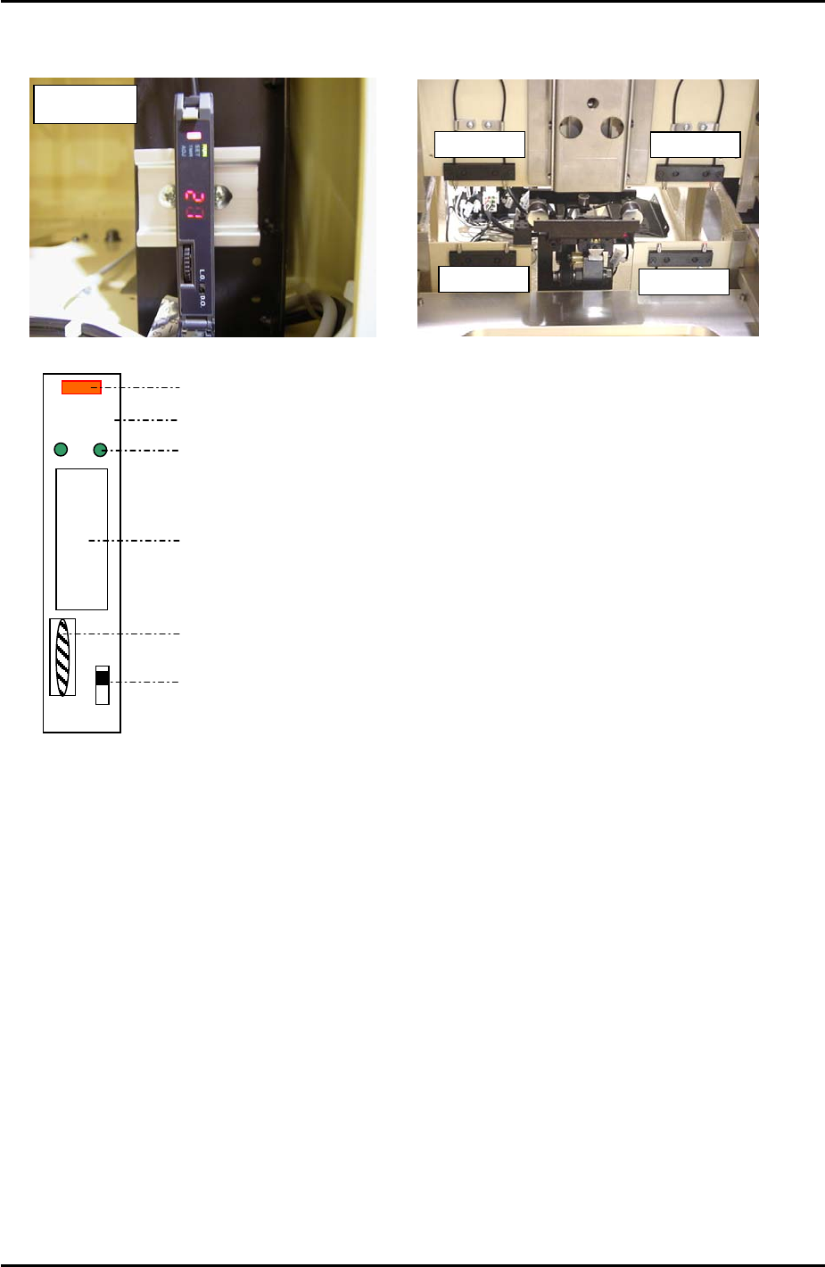
8.16 Tray Pallet Interference Check Sensor Amplifier Adjustment
A
mplifie
r
Sensors
Sensors
Sensors
Sensors
DO LO
RUN
SET
TMR
A
D
J
Digital Display
Operation Light
Mode Lights
Mode Display
Dial Switch
L-ON/D-ON Changeover Switch
1. Press the dial switch once [the RUN light in the Mode Display flashes and “AA” is
displayed on the Digital Display].
2. Turn the dial switch so that the Mode Display turns from RUN to SET.
3. Press and hold the dial switch for more than 3 seconds [HP displays on the Digital
Display and the Mode Lights come ON].
4. Press the dial switch once [SET in the Mode Display flashes and “2P” is displayed on the
Digital Display].
5. Press the dial switch once [“2P” displayed on the Digital Display flashes].
6. Keep turning the dial switch until numbers (0~100), are displayed on the Digital Display
and the Mode Lights come ON.
7. Confirm that the value displayed on the Digital Display is greater than 3.
8. Turn the dial switch until a flashing “2P” displays on the Digital Display.
9. Make sure the sensor is not blocked and press the dial switch once [the 2 in “2P”
Fuji Machine Mfg. Co., Ltd. Okazaki
SMT Equipment Quality Assurance Dept.
8 – 11 CS Section