XP Type II 工程师培训手册 (2.0).pdf.pdf - 第78页
FK-9F98-34 XP T ype II Series T raining T ext for Service Engineers Edition 2.0 XP142E – Chapter 6 Proper Dat a Measurement s Page 19 of 30 6.15 Measuring the Maximum Nozzle Height 1. Equipment: Lever type dial gage (0.0…
FK-9F98-34 XP Type II Series Training Text for Service Engineers
Edition 2.0 XP142E – Chapter 6 Proper Data Measurements Page 18 of 30
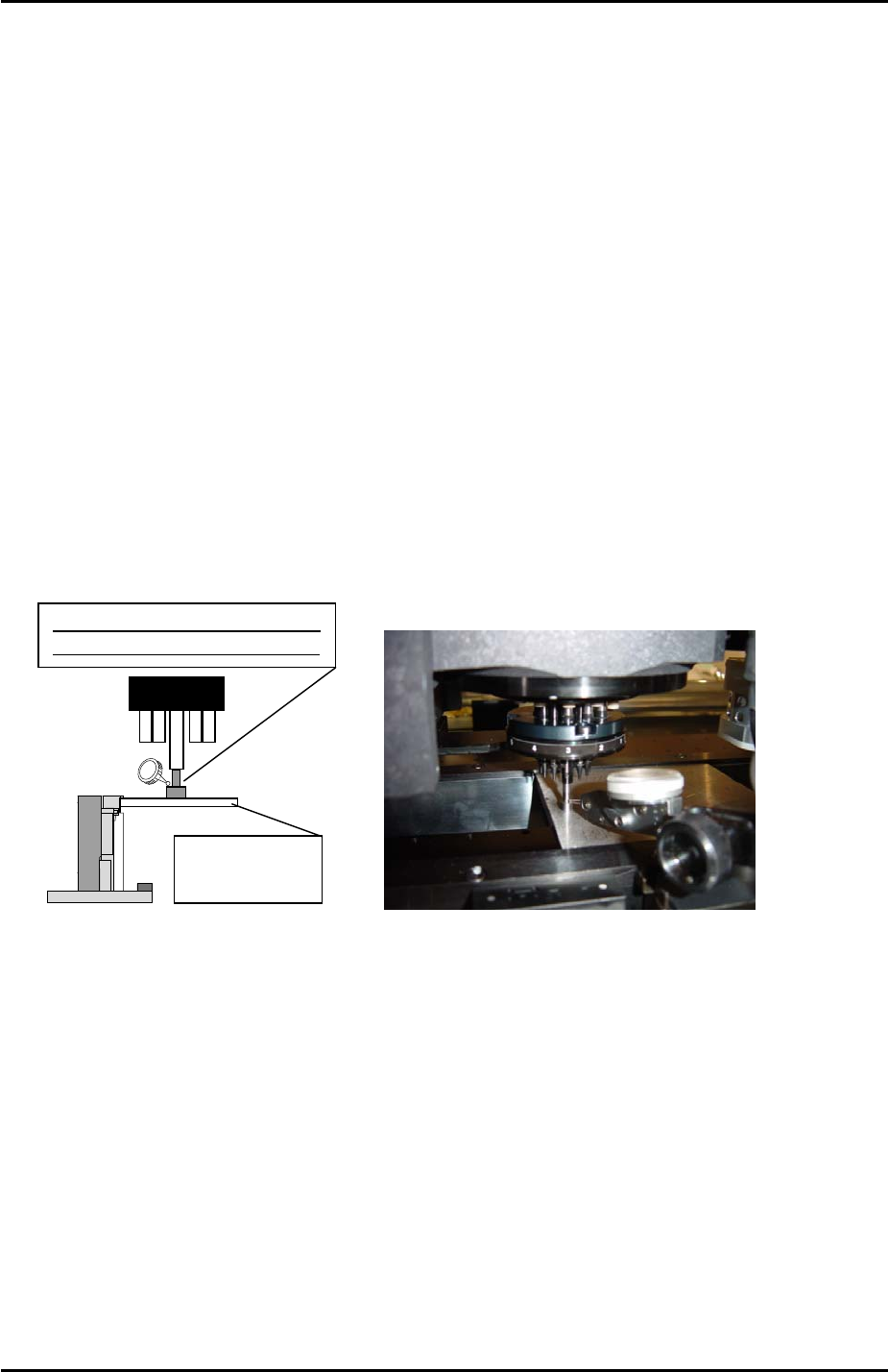
6.14 Measuring Z0
1. Equipment: Lever type dial gage (0.01mm). Plate jig (AJPJ-0060). Nozzle jig
(A5706ADEAJ8100).
2. Refer to the piston height measurement results recorded in chapter 3.3, to identify the
highest piston.
3. Move the highest piston to the front of the machine and install the nozzle jig on the
piston.
4. Clamp the plate jig in the main conveyor.
5. Inch the nozzle jig above the plate jig and then press the emergency stop button to cut
the 200v power supply to the servos.
6. Set the Q axis pusher to 0 degrees and align the pusher and piston.
7. Manually descend the Z-axis until the nozzle jig contacts the plate jig.
8. Set the dial gage on the nozzle jig and then raise the Z-axis until the dial indicator starts
to move. This point is Z0.
Plate jig
A
JPJ-0060
Pickup height measuring
nozzle jig (A5706ADEAJ8100)
9. Select [Maintenance C] – [Proper Data Editor] – [Machine Origin] – [Z Board Surface] –
[Direct Servo Input] to save the current Z-axis counter value to proper data.
10. Note: components higher than 0.3mm are all placed at Z0. The spring in the nozzle
cushions the contact between component and panel during placement. Components with
heights of 0.3 or less are placed at Z0 – (minus) 0.3mm.
Fuji Machine Mfg. Co., Ltd. Okazaki
SMT Equipment Quality Assurance Dept.
6 – 18 CS Section
FK-9F98-34 XP Type II Series Training Text for Service Engineers
Edition 2.0 XP142E – Chapter 6 Proper Data Measurements Page 19 of 30
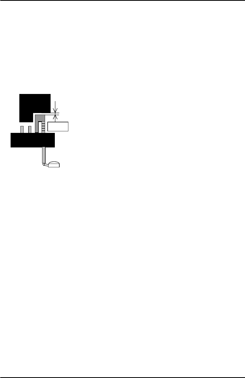
6.15 Measuring the Maximum Nozzle Height
1. Equipment: Lever type dial gage (0.01mm).
2. Refer to the piston height measurement results recorded in chapter 3.3, to identify the
highest piston.
3. Move the highest piston to the front of the machine.
4. Set the Q axis pusher to 0 degrees and align the pusher and piston.
5. Set the dial gage on the piston tip.
0.1mm
6. Lower the Z-axis and use the dial indicator to find the point where the pusher and piston
first contact.
7. Raise the Z-axis 0.1mm from this point and select [Maintenance C] – [Proper Data Editor]
– [Nozzle Position] – [Z_NzlPosZH] – [Direct Servo Input] to save the current Z-axis
counter value to proper data.
8. Rotate the Q axis pusher to confirm that at this height there is no interference between
the nozzle pistons and the pusher.
9. Once this proper data item has been input it is safe to use the “Retract Head” command
in the [Production] screen.
Fuji Machine Mfg. Co., Ltd. Okazaki
SMT Equipment Quality Assurance Dept.
6 – 19 CS Section
FK-9F98-34 XP Type II Series Training Text for Service Engineers
Edition 2.0 XP142E – Chapter 6 Proper Data Measurements Page 20 of 30
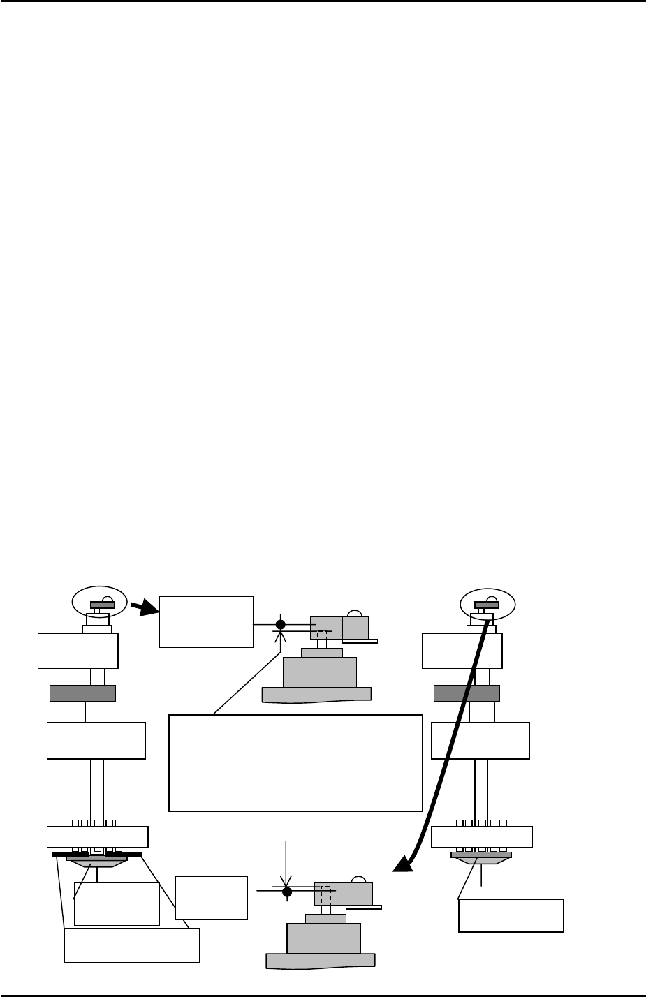
6.16 Reset Cylinder
1. Select [Maintenance A] – [I/O Check] – [Y01F ResetCylinder] – ON to raise the reset
cylinder.
2. Confirm that the clearance between the reset cylinder and the vacuum/air blow pins is
within the range 0 to 0.50mm. This clearance is non-adjustable, so if outside of the
range, please contact Fuji.
Sensor Adjustment
1. Select [Maintenance A] – [I/O Check] – [Y01F ResetCylinder] – OFF to lower the reset
cylinder.
2. Place a 1.0mm feeler gage between the reset cylinder and the vacuum/air blow pins.
3. Select [Maintenance A] – [I/O Check] – [Y01F ResetCylinder] – ON to raise the reset
cylinder making sure that the 1.0mm feeler gage remains between the reset cylinder and
the Vacuum/air blow pins. Take care not to trap your fingers when carrying this out.
4. Select [Maintenance A] – [I/O Check] – [X012 ResetCylUpChk] so that the sensor status
can be monitored.
5. Loosen the reset cylinder sensor bracket bolts and lower the sensor until it comes ON,
then raise it until it just comes OFF. Lock the sensor bracket at this position.
6. Lower and then raise the reset cylinder and confirm that with the 1.0mm feeler gage in
place the reset cylinder sensor does not come ON.
7. Remove the 1.0mm feeler gage and raise the reset cylinder, confirm that the reset
cylinder sensor is ON at this position.
Reset
C
y
linde
r
1.0mm feeler gauge
Sensor
turns On
Sensor turns
OFF
Insert the 1.0mm feeler gauge. When the
reset cylinder is up, the upper limit check
sensor should turn Off. And sensor
should turn On when the 1.0mm feeler
gauge is removed.
Reset Cylinder
Fuji Machine Mfg. Co., Ltd. Okazaki
SMT Equipment Quality Assurance Dept.
6 – 20 CS Section