np134 mechanical reference-1.1e.pdf.pdf - 第105页
Notes: Part 4 Chapter 2 Connecting the Air Edition 1.0 4-2-2 NP-134E/134ME Mechanical
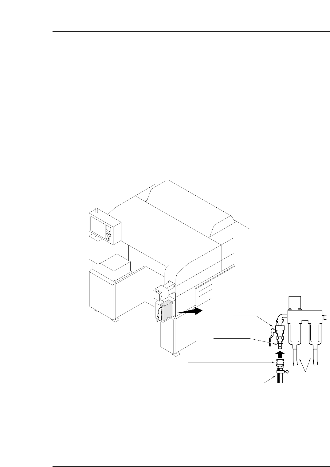
2. Connecting the Air
Objective
Connect the air hose to the machine and adjust the regulator so that sufficient air
pressure is supplied to the machine.
Procedure
1. Connect the drain hoses to the filter regulator.
Note: The drain hoses should be ø 4 ~ 5 (inside) and ø 10 (outside).
2. Connect the hose to the air inlet.
3. Pull up on the regulator knob to release the lock.
4. Adjust the valve handle until the pressure level indicated at the regulator shows
0.5 MPa (5 kgf/cm
2
).
5. Push the regulator knob down to lock it.
Note: The hose is not supplied by Fuji.
NP1MS051
400SH ( for 1/2" hose) socket
Drain hoses
Hose
400PM plug
Handle
Part 4 Chapter 2 Connecting the Air
Edition 1.0 4-2-1 NP-134E/134ME Mechanical

Notes:
Part 4 Chapter 2 Connecting the Air
Edition 1.0 4-2-2 NP-134E/134ME Mechanical
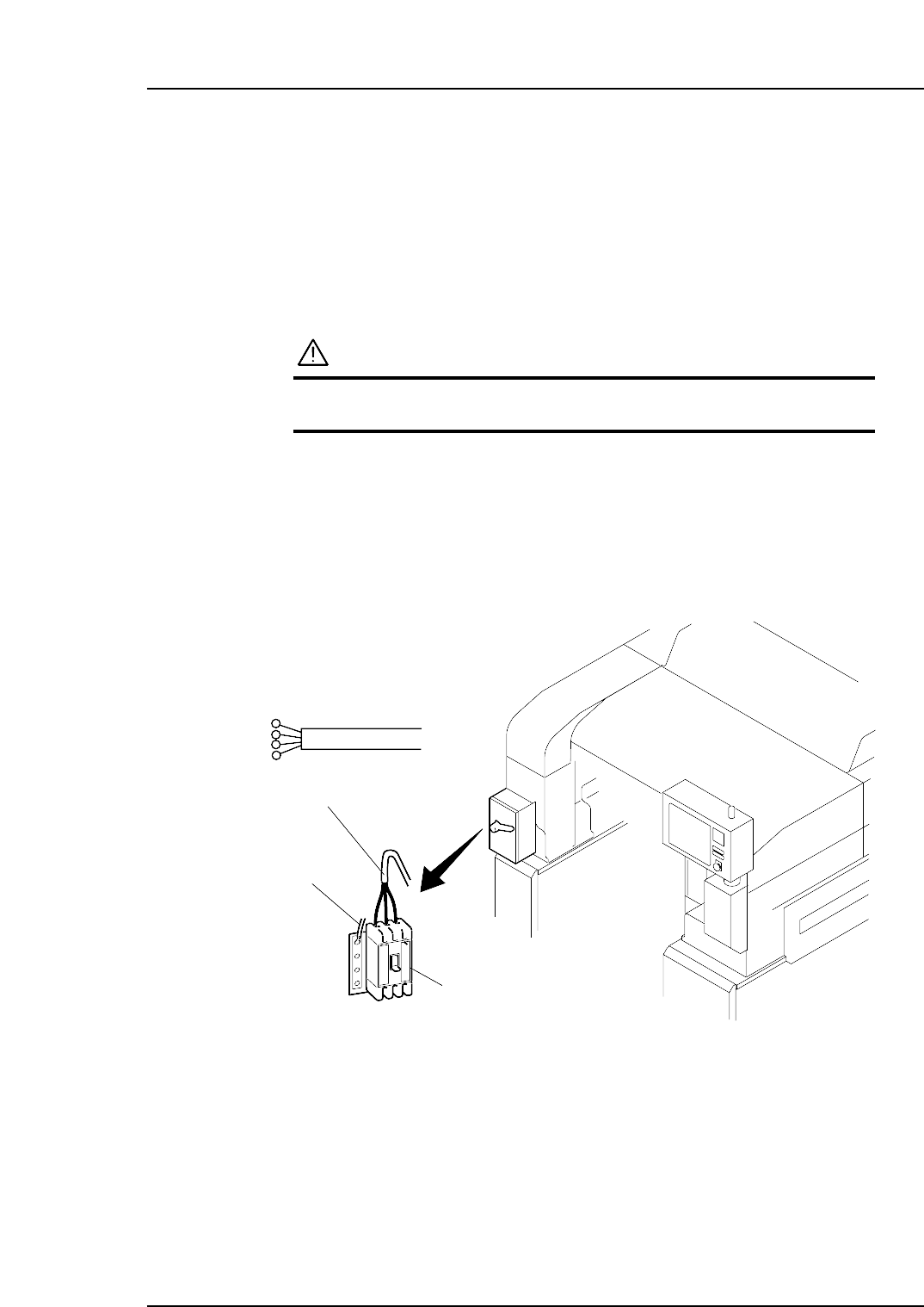
3. Electric Power Supply & Transformer Wiring
Objective
Wire the transformer inside the machine so that its voltage matches the supplied voltage.
Procedure
DANGER
Make sure the external power supply is switched off before
attempting this procedure.
Electric Power Supply
The power cable should be inserted into the machine through the power cable inlet.
The power capacity is 4.5 KVA.
Be sure to connect the machine to a power supply which exceeds this capacity.
The 3-phase power cable should be connected to the main breaker, and the ground calbe
should be connected to the dedicated ground terminal.
Main breaker
Three-phase electric wire
Ground wire
NP1MS052
Part 4 Chapter 3 Electric Power Supply & Transformer Wiring
Edition 1.0 4-3-1 NP-134E/134ME Mechanical