np134 mechanical reference-1.1e.pdf.pdf - 第106页
3. Electric Power Supply & T ransformer Wiring Objective Wire the transformer inside the machine so that its voltage matches the supplied voltage. Procedure DANGER Make sure the external power supply is switched off …

Notes:
Part 4 Chapter 2 Connecting the Air
Edition 1.0 4-2-2 NP-134E/134ME Mechanical
3. Electric Power Supply & Transformer Wiring
Objective
Wire the transformer inside the machine so that its voltage matches the supplied voltage.
Procedure
DANGER
Make sure the external power supply is switched off before
attempting this procedure.
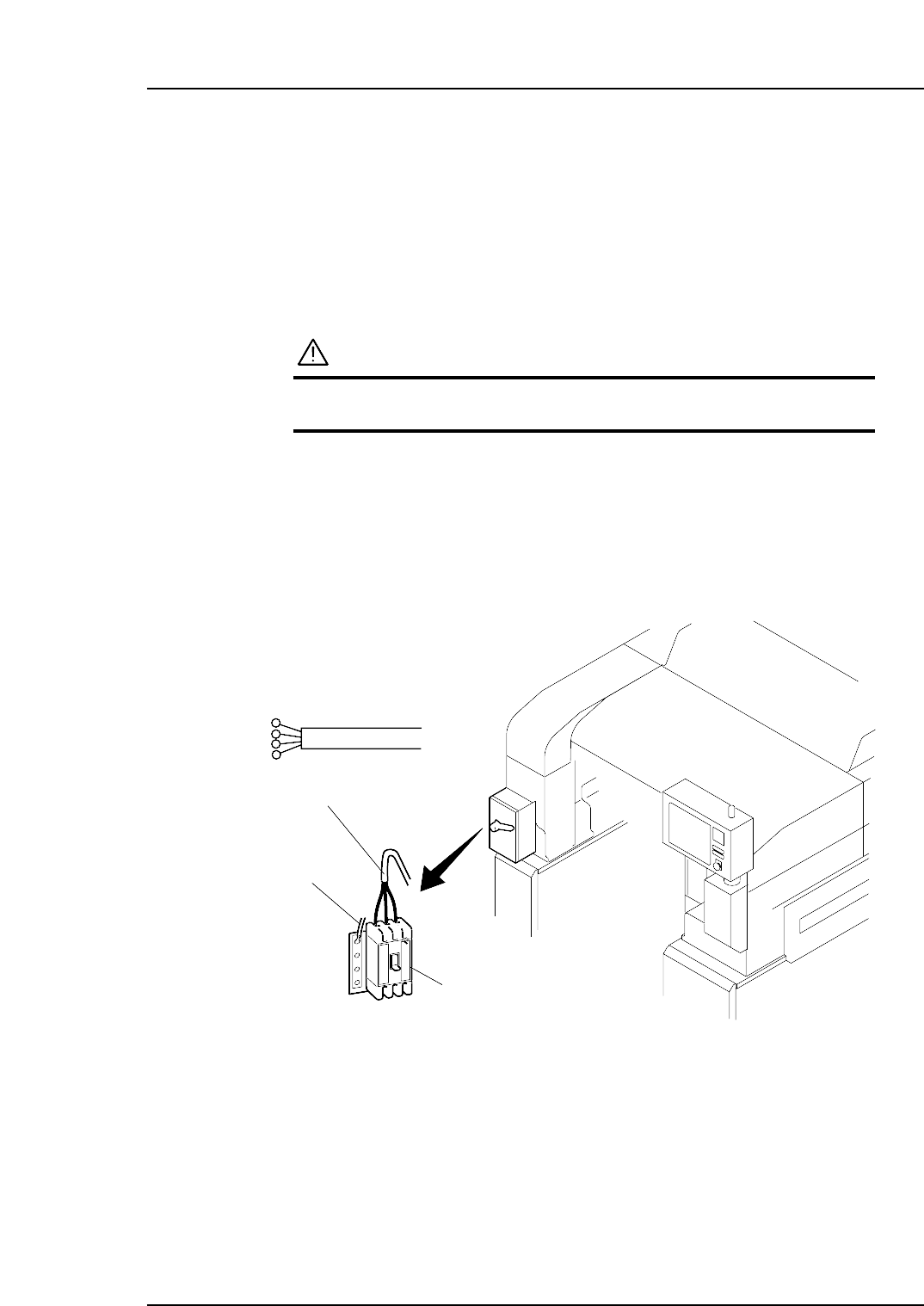
Electric Power Supply
The power cable should be inserted into the machine through the power cable inlet.
The power capacity is 4.5 KVA.
Be sure to connect the machine to a power supply which exceeds this capacity.
The 3-phase power cable should be connected to the main breaker, and the ground calbe
should be connected to the dedicated ground terminal.
Main breaker
Three-phase electric wire
Ground wire
NP1MS052
Part 4 Chapter 3 Electric Power Supply & Transformer Wiring
Edition 1.0 4-3-1 NP-134E/134ME Mechanical
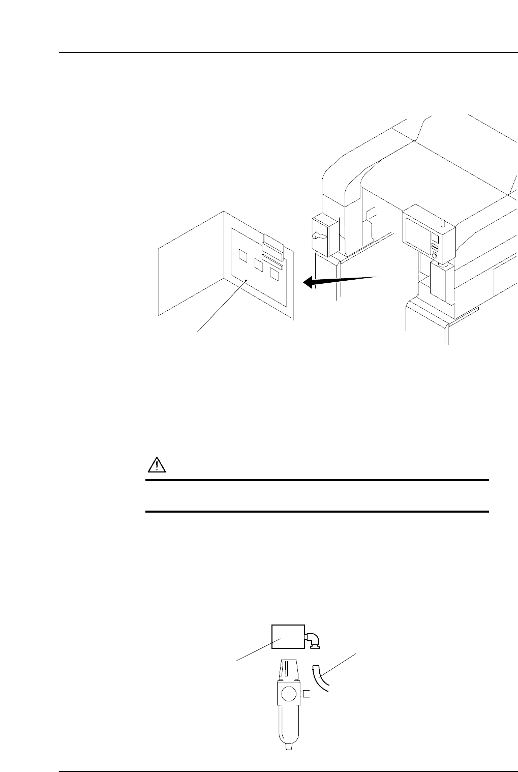
Wiring the Transformer
1. Remove the transformer box cover.
2. Wire the primary taps to match the supplied voltage.
Checking the Three Phases
Confirm that the three phasee have been connected by checking the direction the motors
rotate in.
CAUTION
The machine may be damaged if the motor rotates in the
reverse direction.
1. Supply 100V to the machine.
2. Disconnect the tubing from the pressure switch next to the regulator.
3. With your finger, check the flow of air of the outlet. If there is suction, the wiring
is correct. If there is air blown from the outlet, it means the three phases are not
connected properly and need to be rewired. In this case, rewire the wiring of the
U and V phase, and then check the wiring again using the same method.
NP1MS054
Pressure switch
Tube
NP1MS053
Transformer box
Part 4 Chapter 3 Electric Power Supply & Transformer Wiring
Edition 1.0 4-3-2 NP-134E/134ME Mechanical