np134 mechanical reference-1.1e.pdf.pdf - 第34页
(d) CPU Board This board performs the processing required for machine operation. It is equipped with a RAM where Proper data and program data, etc., are stored. This is the memory board for nozzle and parts data required…
Electrical Control System
Operation Box
The operation box is equipped with the buttons (and touch-screen monitor) required to
operate the machine.
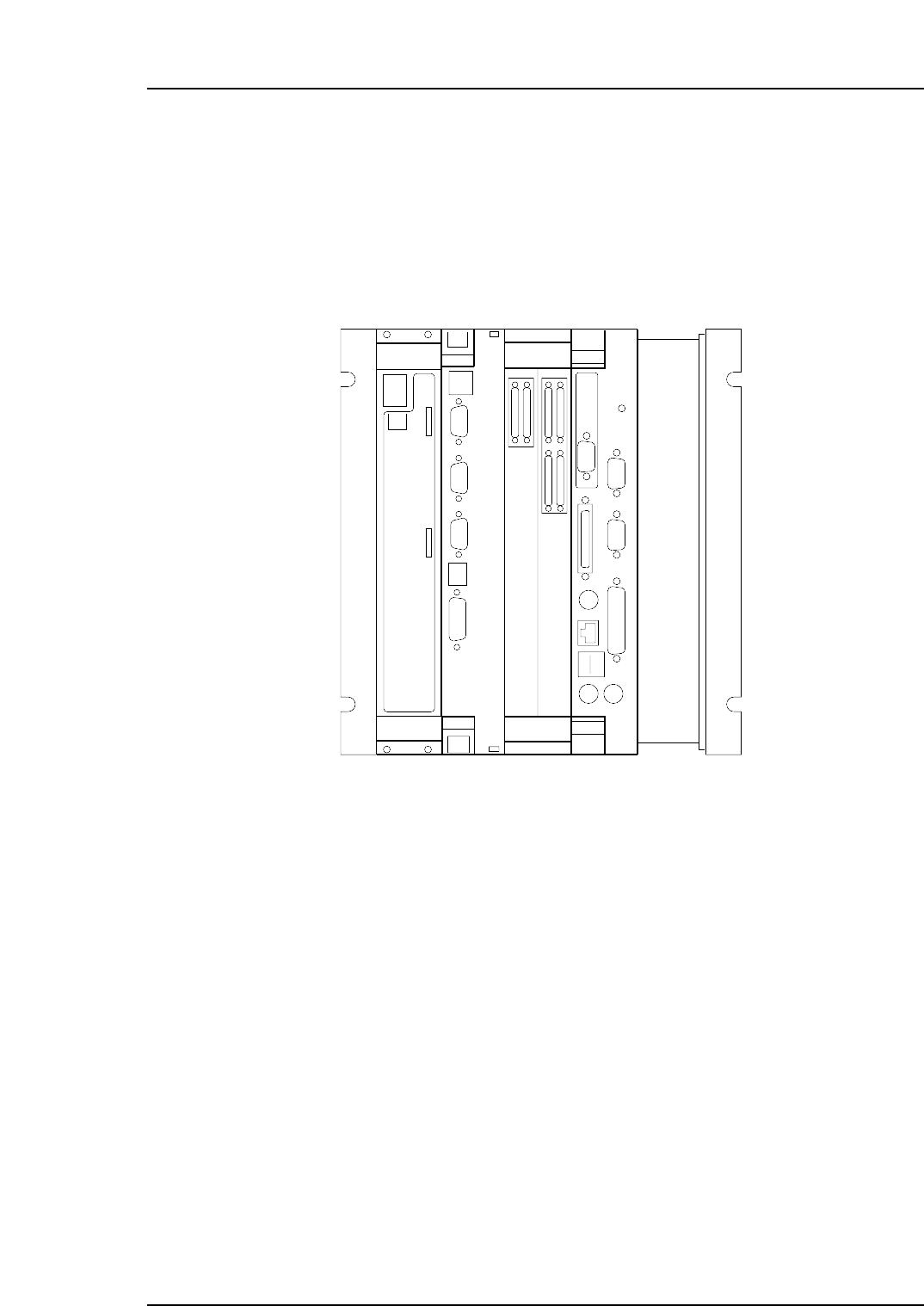
Control Box
The control box contains the electrical circuitry required for machine control.
The control box also contains control boards. Descriptions of each of these boards are
given below.
(a) I/O board
This board transfers signals from sensors and switches to the CPU board, and
controls relays, valves and PFU-4E/5E etc., in accordance with signals from the
CPU board.
(b) Vision Processing Board
This board processes data from the CCD camera which enables parts to be
mounted accurately.
(c) Servo board.
This is a servo motor board. It controls the travel speeds and stop positions for the
following 12 axes:
Y1, X1, I1, Q1, Z1, S1
Y2, X2, I2, Q2, Z2, S2
NP1MN055
(a) (b) (c) (d)
COMA
RESET
COMB
MEZ01 MEZ01
CN1(IN)
CN2(OUT)
Part 1 Chapter 3 Functions of Each Part
Edition 1.0 1-3-3 NP-134E/134ME Mechanical

(d) CPU Board
This board performs the processing required for machine operation. It is equipped
with a RAM where Proper data and program data, etc., are stored.
This is the memory board for nozzle and parts data required for vision processing.
Data stored here is backed up at a battery powered memory card, and will not be
lost at power ON/OFF or reset operations. In addition to communication tasks
the CPU board contains an integrated VGA board for monitor control.
Servo Box
The servo box contains the boards which control the servo amplifier and the parts
mounting, board transfer, and nozzle change systems. Except when performing servo
amplifier maintenance, users should not tamper with the contents of this box.
Part 1 Chapter 3 Functions of Each Part
Edition 1.0 1-3-4 NP-134E/134ME Mechanical
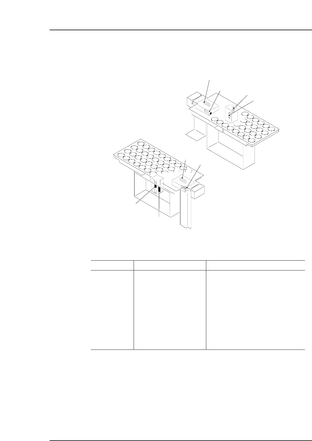
4. Sensor Positions
Nozzle Station
X05A
X05B
X058
X059
X05E
X05F
X05C
X05D
N CHGR UP END1
N CHGR DN END1
NZL SHTR OPN1X
NZL SHTR CLS1X
N CHGR UP END2
N CHGR DN END2
NZL SHTR OPN2X
NZL SHTR CLS2X
NOZZLE STATION UP1
NOZZLE STATION DOWN1
NOZZLE SHUTTER OPEN CHECK1
NOZZLE SHUTTER CLOSE CHECK1
NOZZLE STATION UP2
NOZZLE STATION DOWN2
NOZZLE SHUTTER OPEN CHECK2
NOZZLE SHUTTER CLOSE CHECK2
NP1Tb050
Sensor No.
INDICATION SIGNAL NAME
NP1MN057
X059
X05A
X05B
X058
X05F
X05E
X05D
X05C
(Side 1)
(Side 2)
Part 1 Chapter 4 Sensor Positions
Edition 1.0 1-4-1 NP-134E/134ME Mechanical