np134 mechanical reference-1.1e.pdf.pdf - 第9页
Safety Guidelines Fuji machines are designed and pr oduced with safety as one of our main considerations. However , even a perfectly designed machine can be damaged, or someone can still be injured if the user does not f…

Contents – List of Current Pages
Edition 1.1 vi NP-134E/134ME Mechanical
Part 3 Maintenance
1. Cleaning................................................................(Edition 1.0) ......3-1-1
1.1 Cleaning the Nozzle (Weekly) .........................................................................3-1-1
1.2 Cleaning the Filter Inside the Nozzle Sleeve of(Weekly).................................3-1-2
1.3 Cleaning the Nozzle Fluorescent Seal (Monthly).............................................3-1-3
1.4 Emptying the Reject Parts Box (Every 8 Hours)..............................................3-1-4
1.5 Cleaning the Parts Camera Prism (Monthly)...................................................3-1-5
1.6 Emptying the PFU Waste Tape Box (Every 2 Hours)......................................3-1-7
1.7 Cleaning the Filter Regulator (Monthly)...........................................................3-1-8
1.8 Cleaning the Inside of the Machine (Weekly)..................................................3-1-9
1.9 Cleaning the Nozzle Shaft (Every 1000 Hours).............................................3-1-10
1.10 Cleaning the Y-axis Motor Cooling Fan Filter (Monthly)..............................3-1-12
Cleaning Check Points ........................................................................................3-1-13
2. Lubrication.............................................................(Edition 1.1) ......3-2-1
Precautions During Lubrication..............................................................................3-2-1
Types of Lubricants ...............................................................................................3-2-1
Grease Gun Kit......................................................................................................3-2-2
Lubrication Instructions..........................................................................................3-2-3
2.1 XY-Robot Lubrication (Y-axis LM Guide).........................................................3-2-4
2.2 In-conveyor Lubrication ...................................................................................3-2-5
2.3 Out-conveyor Lubrication.................................................................................3-2-6
2.4 Main Conveyor Lubrication..............................................................................3-2-7
2.5 Head Index Lubrication....................................................................................3-2-8
2.6 Nozzle Station Lubrication...............................................................................3-2-9
2.7 Z-axis Lubrication ..........................................................................................3-2-10
2.8 PFU’s Tape Cutter Lubrication ......................................................................3-2-11
2.9 PFU’s Caster Lubrication...............................................................................3-2-12
Lubrication Check Points.....................................................................................3-2-13
3. Replacing Consumable Parts................................(Edition 1.0) ......3-3-1
3.1 Replacing Nozzles...........................................................................................3-3-1
3.2 Replacing the Nozzle's Fluorescent Seal ........................................................3-3-2
3.3 Replacing the Mark Camera Lamp..................................................................3-3-4
3.4 Conveyor Belt Replacement............................................................................3-3-5
3.5 Parts Camera UV Lamp Replacement ............................................................3-3-7
3.6 Replacing the Filter Regulator.........................................................................3-3-9
3.7 Replacing the Vacuum Pump (Every 1000 Hours)........................................3-3-10
3.8 Replacing the PFU Photo Link Board Fuse...................................................3-3-12
4. Adjustment............................................................(Edition 1.0) ......3-4-1
4.1 Adjusting the Conveyor Sensor Delay Times..................................................3-4-1
Part 4 Setup
1. Leveling the Machine............................................(Edition 1.0) ......4-1-1
2. Connecting the Air.................................................(Edition 1.0) ......4-2-1
3. Electric Power Supply & Transformer Wiring........(Edition 1.0) ......4-3-1
4. Connecting the Data Cable...................................(Edition 1.0) ......4-4-1

Safety Guidelines
Fuji machines are designed and produced with safety as
one of our main considerations. However, even a
perfectly designed machine can be damaged, or someone
can still be injured if the user does not follow the safety
rules. It is the responsibility of the user to make sure all
safety rules are followed during operation and
maintenance.
Be sure to read these safety rules before operating the
machine. Keep this manual close to hand when
operating the machine.
1. About Symbols
To avoid injury to persons and damage to the machine, Fuji employs a number of messages
and symbols that are used in manuals and on the machines. Be sure you understand the
meanings of these symbols before reading the manual.
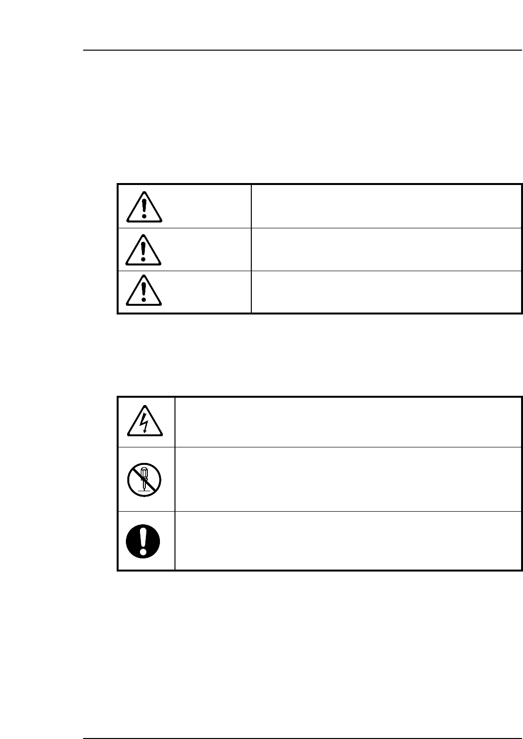
Hazard warnings are divided into the following three classes:
Safety Guidelines
Edition 1.1 1 NP-134E/134ME Mechanical
DANGER
The hazard or unsafe practice will cause severe injury or
death.
WARNING
The hazard or unsafe practice may cause severe injury or
death.
CAUTION
The hazard or unsafe practice may lead to personal injury
or damage to the machine.
To distinguish the type of hazard, the following symbols are used in combination with the
ones above.
Hazard Alert
A triangle is used to draw your attention to a hazard. The symbol inside the
triangle indicates the nature of the hazard (in this case electrical shock).
Prohibition
A circle with a diagonal line inside is used to draw your attention to an
operation that is prohibited. The symbol inside the circle indicates the nature
of the operation (in this case disassembly).
A circle with an exclamation mark is used to draw your attention to a
mandatory action. In other words, you are required to carefully carry out the
given instructions.