SYS-CP842-1.1E.pdf - 第34页
SYS-CP842-1.1E 2.The Machine CP-842E / CP-842ME System Reference 25 CYCLE STOP button This button can be used dur ing operation to stop the machine at the end of the current movement. Unlike the EMERGENCY STOP bu tton, p…
2.The Machine SYS-CP842-1.1E
24 CP-842E / CP-842ME System Reference
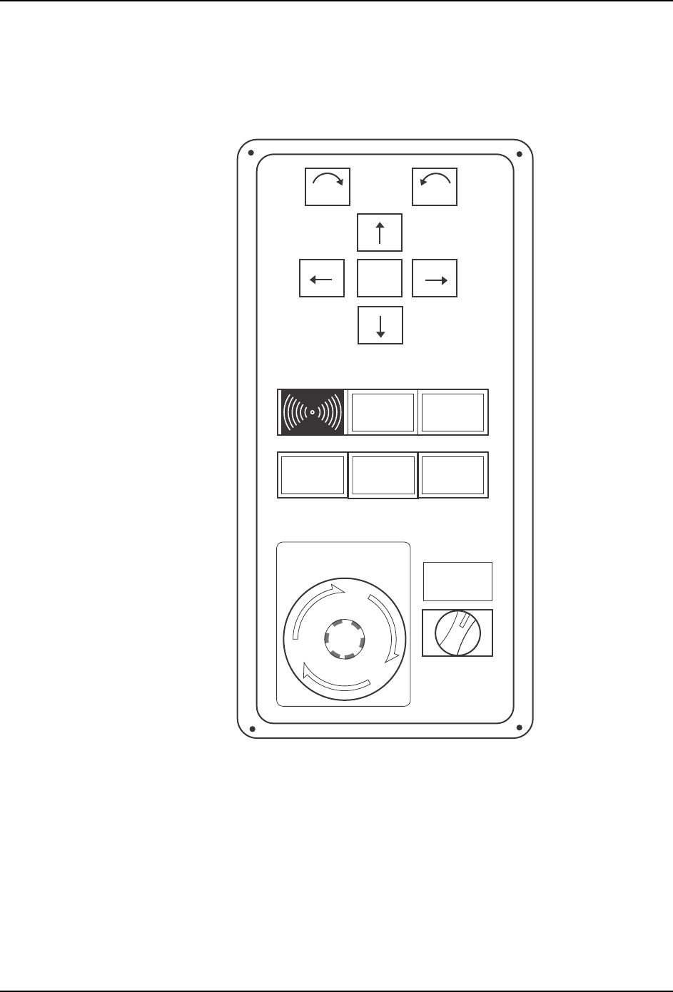
2.1.4 Machine Controls
The machine uses a combination of a touch screen and conventional push buttons.
The major buttons on the operation box and touch screen are detailed below.
POWER ON lamp
This indicator is lit when the main breaker is set to the ON position.
SYSTEM ON button
This button turns on the power supply to the machine and boots up the control software.
START button
This button is pushed to commence operation. This button can only be pushed when the
machine is in START ready status (i.e., when the button is flashing).
POWER
ON
READY
ON
Side 1
START
EMERGENCY
STOP
SYSTEM
ON
ENABLE
LOCK
CYCLE
STOP
F
θ
θ
C73OM007

SYS-CP842-1.1E 2.The Machine
CP-842E / CP-842ME System Reference 25
CYCLE STOP button
This button can be used during operation to stop the machine at the end of the current
movement. Unlike the EMERGENCY STOP button, pressing CYCLE STOP does not cut
the 200V power.
READY ON button
This button cancels an error status and resupplies the 200V power to the servo system.
EMERGENCY STOP button
Pressing an EMERGENCY STOP button cuts the 200V power to the machine and stops
operation immediately. This button locks in position when pressed, and must be turned
clockwise to release it.
Users should familiarize themselves with the locations of the EMERGENCY STOP buttons
prior to operating the machine. In addition to the button on the front of the machine (shown
in the figure above), further EMERGENCY STOP buttons are positioned at the rear of the
machine, and on the optional MTU safety fence.
Refer to the illustration in Chapter 5 of the Safety Guidelines to confirm the positions of all
the EMERGENCY STOP buttons.
Side 1/2 ENABLE/LOCK switch
Toggle this switch to enable operation at the desired side; front (Side 1) or rear (Side 2), of
the machine. Operation at a given side of the machine cannot be enabled if the switch at
the other side of the machine is set to LOCK.
Power Off button (touch screen command that displays when the EMERGENCY
STOP button is pushed)
The [Power Off] button is used to turn off the main power to the machine.
This button can only be pressed after the EMERGENCY STOP button has been pushed.
2.The Machine SYS-CP842-1.1E
26 CP-842E / CP-842ME System Reference
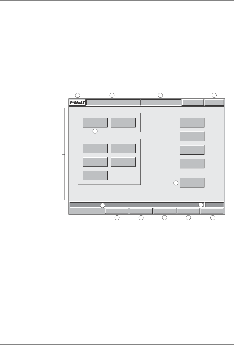
2.1.5 Touch Screen
The operator issues commands to the machine from the touch screen at the front or rear of
the machine. Each screen that appears at the touch screen contains a number of command
buttons, which display the commands associated with the selection. Some screens, as in
the example below, are divided into sections with related commands being grouped
together.
Although different commands display at each screen, the title bar, information bar, and
command bar commands which are common to all screens (sections A to M in the figure
below) are explained below. Refer to part 3 of this manual for a detailed explanation of the
command hierarchy.
Title bar
a. Press the [FUJI] button to display version information for the machine control
software, vision system software, and operating system.
b. The name of the active program displays at this section of the title bar.
c. The name of the current screen displays at this section of the title bar.
d. This button displays in red if an error occurs. When red, this button can be pressed
at any screen to return to the red error screen.
Main area
e. The command buttons in the main section of each screen can be pressed to access
further related commands. Refer to part 3 for a detailed explanation of the command
hierarchy.
f. The [Close] button is available on all screens except the [Main] screen. Press this
button once to return to the previous screen. Press this button in succession to return
Command section
Screen name
Command section
Select a command.
Command section
COMMAND COMMAND COMMAND
COMMAND
COMMAND
COMMAND
Close
COMMAND COMMAND
COMMAND COMMAND
COMMAND
FRONT
Vision
0
Host Servo Count
Operator CallABC_PROG Error
JOG:XY CAM
Title bar
Main area
Infomation bar
Command bar
C73OM008a
a b cd
e
f
g
h
i
j
k lm
Set Switch