00192809-01.pdf - 第56页
5 Configuration User M anual V 1.15 - Productivity Lift 5.23 Run out time up Software version V 40. 1 1 Edition 01/2001 48 5XQRXWWLPHXS A time that c an be s et to secu re the p ositioni ng of the lower li ft in …
User Manual V 1.15 - Productivity Lift 5 Configuration
Software version V 40.11 Edition 01/2001 5.21 Travelling speed
47
7UDYHOOLQJVSHHG
The speed at which the lower lift travels between the two final positions. The value to be entered
is a percentage value of the entire motor output.
The setting is a percentage of the motor rating. The default setting are 80%.
5XQRXWWLPHGRZQ
A time that can be set to secure the positioning of the lower lift in its final lower position. This guar-
antees that the lift has reached its final position before a PCB is transferred or delivered.
The unit of value is [0.01s]. The default setting are 002.
Travelling speed
080
Run out time down
002
5 Configuration User Manual V 1.15 - Productivity Lift
5.23 Run out time up Software version V 40.11 Edition 01/2001
48
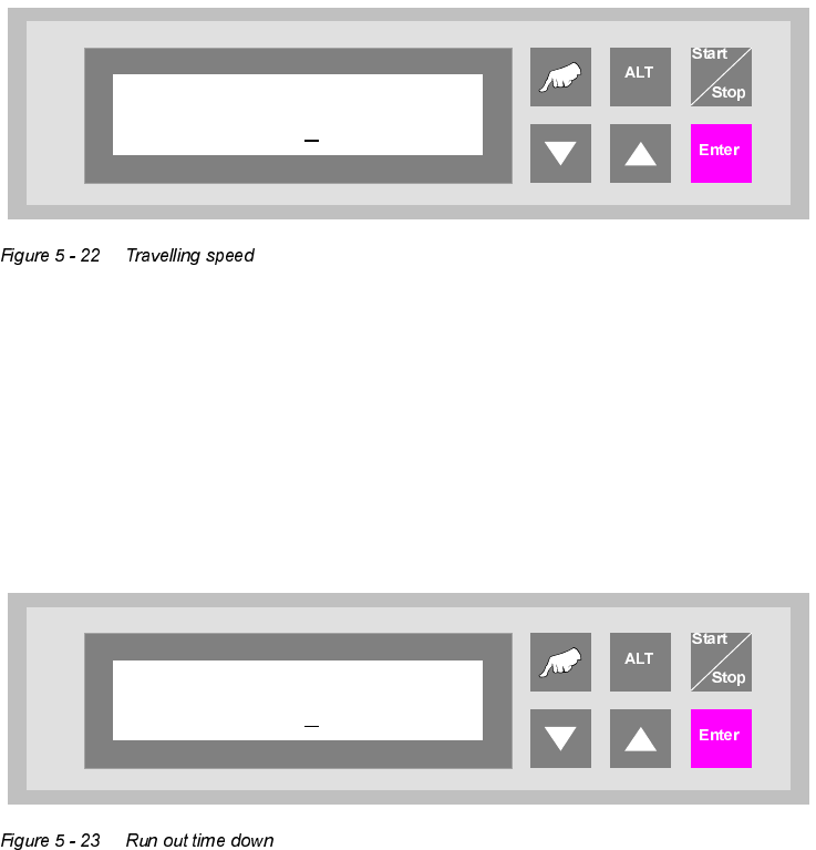
5XQRXWWLPHXS
A time that can be set to secure the positioning of the lower lift in its final upper position. This guar-
antees that the lift has reached its final position before a PCB is transferred or delivered.
The unit of value is [0.01s]. The default setting are 007.
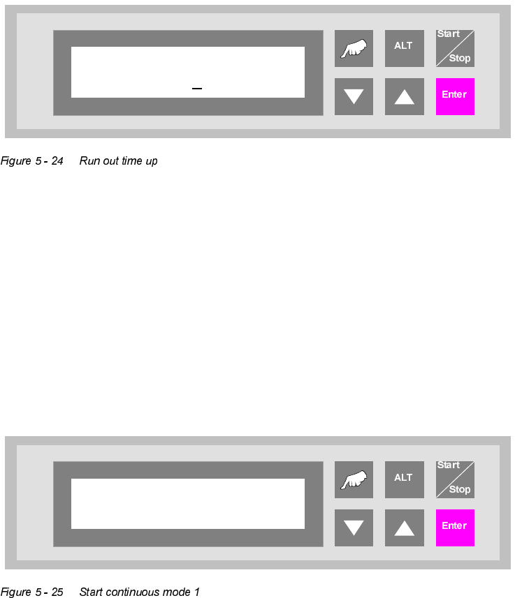
6WDUWFRQWLQXRXVPRGH
This continuous operation mode can be implemented with two lift modules and one placement
machine. A PCB is transported on the upper transport level from the lift to the placement machine,
on to the next lift and, from there, back again to the front lift on the underfloor conveyor. This cycle
is repeated until the continuous operation mode is interrupted.
The continuous operation mode is initiated from this menu using the "Hand" key. The "Start/Stop"
key is used to interrupt it.
Run out time up
007
Start continuous
mode 1?
User Manual V 1.15 - Productivity Lift 5 Configuration
Software version V 40.11 Edition 01/2001 5.25 Start continuous mode 2
49
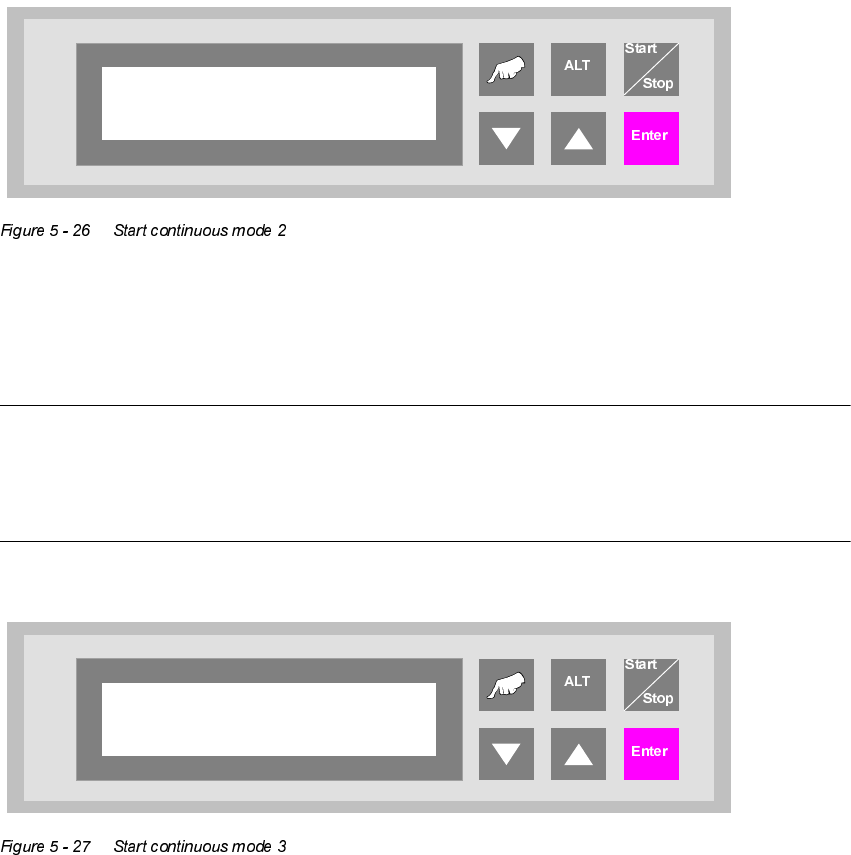
6WDUWFRQWLQXRXVPRGH
This continuous mode can run with at least two or more lift modules and the according number of
conveyors. No placement systems are needed. A PCB is driven down by lift 1, transported via the
conveyor to lift 2, where it is moved first up and then down and transferred to the next lift via a
conveyor etc. This cycle repeats until the running mode is interrupted. After the last lift an loading
unit can be placed which puts the PCBs into magazines. The unloading of PCBs into the first lift
can be made by a input station.
The continuous operation mode is initiated from this menu using the "Hand" key. The "Start/Stop"
key is used to interrupt it.
6WDUWFRQWLQXRXVPRGH
127(
This continuous operation mode can only be implemented by the manufacturer using special test
equipment. An attempt by a user to initiate this continuous operation mode produces an error mes-
sage.
Start continuous
mode 2?
Start continuous
mode 3?