00192809-01.pdf - 第60页
6 Set-up mode User M anual V 1.15 - Productivity Lift 6.1 Identity number Software version V 40. 1 1 Edition 01/2001 52 ,GHQWLW\QXPEHU This sele ction can be used to assign an identifi cation n umber to the follo wi…
User Manual V 1.15 - Productivity Lift 6 Set-up mode
Software version V 40.11 Edition 01/2001
51
6HWXSPRGH
In set-up mode, it is possible to enter and modify parameters that do not serve the basic setting
of the system, but that, for example, show the values dependent on the size of the machine type.
Press the "ALT" key to access the "set-up mode" menu.
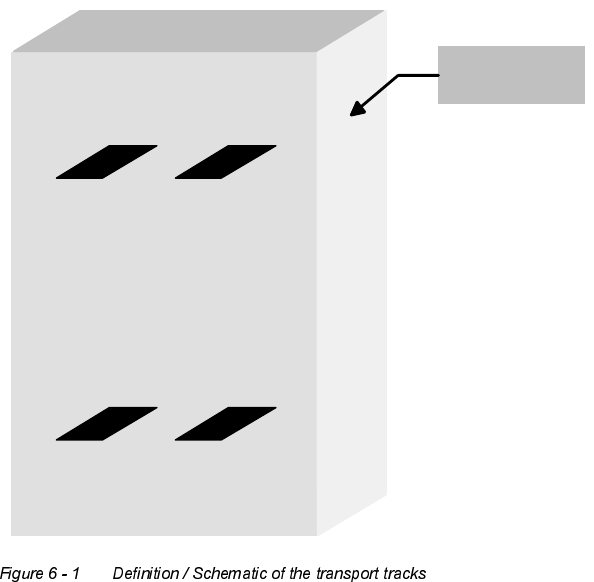
'HILQLWLRQ
View of the direction of transit.
Spur 2
Track 2
Spur 1
Track 1
Spur 4
Track 4
Spur 3
Track 3
Bedienseite
Operating side
6 Set-up mode User Manual V 1.15 - Productivity Lift
6.1 Identity number Software version V 40.11 Edition 01/2001
52
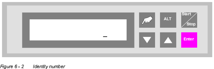
,GHQWLW\QXPEHU
This selection can be used to assign an identification number to the following set of parameters.
When starting the system, only the corresponding PCB number need be called up, and the system
sets the stored parameters automatically. The number consists of two assignment digits and one
eight-digit identification. The assignment digits can be used to call up the parameter set when
starting the system. The eight-digit identification can be changed at random and only serves the
input of user-specific identification numbers. Each number has only one numerical entry.
0DFKLQHW\SH
Here, the type of system is determined, which corresponds to the position and mode of operation
of the device thus required in the production line.
7KHIROORZLQJW\SHVRIPDFKLQHDUHGHILQHGIRUWKH3URGXFWLYLW\/LIW
Input module : If the lift is at the beginning of the Siplace assembly line, this setting must be
selected in machine type. The input module can only transfer printed circuit
boards on transport tracks 1 and 2. Priority is given to attempting to then
transfer the PCBs to the placement machine. If this is not possible, the un-
assembled PCBs are forwarded essentially to track 3 on the lower level and
then transported for the time being to the next lift (intermediate module) or
the placement machine.
Ident number
01 00000001
User Manual V 1.15 - Productivity Lift 6 Set-up mode
Software version V 40.11 Edition 01/2001 6.2 Machine type
53
Cluster module : The intermediate module is located after the input module and is defined as
the intermediate module as long as the subsequent placement machines are
of the same type. The intermediate module accepts either assembled PCBs
from tracks 1, 2 and 4, and transfers them further on track 4, or it accepts
unassembled PCBs from track 3 and attempts to deposit them at the follow-
ing placement machine. If the following placement machine is occupied, the
unassembled PCBs are transported further via track 3 to the next lift or
placement machine.
$OORFDWLRQRIWKHLQOHWVDQGRXWOHWVWRHDFKRWKHU
1. take-over inlet track 1 → hand-over outlet track 4
2. take-over inlet track 2 → hand-over outlet track 4
3. take-over inlet track 3 → hand-over outlet track 1, 2 or 3
4. take-over inlet track 4 → hand-over outlet track 4
In order to prevent the system becoming blocked, only one PCB may be
transferred if the allocated outlet is ready. Fixed priorities are allocated to the
individual transport directions. Inlet tracks 1 and 2 as well as outlet tracks 1
and 2 all have the same priority.
2WKHUZLVHWKHIROORZLQJDSSOLHV
1. take-over inlet track 3 → hand-over outlet tracks 1 and 2
2. take-over inlet tracks 1 and 2 → hand-over outlet track 4
3. take-over inlet track 3 →hand-over outlet track 3
4. take-over inlet track 4 → hand-over outlet track 4
Cross module : The setting "cross module" must always be selected if the type of placement
machine changes in the line. The cross module handles all incoming PCBs
as if they are unassembled. In this way, the PCBs arriving on tracks 1, 2 and
4 are presented to the placement machine for processing. If the following
placement machine is of the same type, PCBs can also be transferred on
track 3 at the cross module if the current placement machine is occupied. If
the cross module is the last lift before the final module, no PCBs may be
transferred on track 3. Similarly, no PCBs may be accepted from the last in-
termediate module before this cross module.