TR7600 SIII_Hardware_en_v_2_0_4.pdf - 第29页
Test Research, Inc . TR7600 SIII Seri es User Gu ide – Hardw are 19 3.8 Burn-In Users can ignore t his section, since only pr ofessional TRI engineers will use below functions. Figure 19: VPLC/Burn-In

Test Research, Inc.
18 TR7600 SIII Series User Guide – Hardware
If you want to re-calibrate the conveyor width, please follow the steps below:
1) Measure the calibration board width.
2) Input the calibration board width in the [Board Width] field.
3) Click [Tick 2] and [Move to Rough] in sequence. The conveyor will move to the
position assigned by you approximately.
4) Measure the conveyor width.
5) Change the fine-tune distance to meet your needs in the [Fin-Tune Distance] field and
then use the [Up Arrow] and [Down Arrow] buttons to fine-tune the conveyor width to
the precise assigned position.
6) Put the calibration board into the machine and slide it on the conveyor to double
confirm the width setup is correct.
7) Click [Tick 3] and [Save to Registry] in sequence to save changes to the registry. The
machine will display the maximum conveyor width based on your calibration. The
maximum conveyor width after calibration should be the same as the default
maximum conveyor width.
Test Research, Inc.
TR7600 SIII Series User Guide – Hardware 19
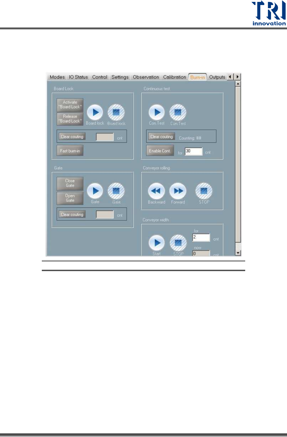
3.8 Burn-In
Users can ignore this section, since only professional TRI engineers will use below
functions.
Figure 19: VPLC/Burn-In
Test Research, Inc.
20 TR7600 SIII Series User Guide – Hardware
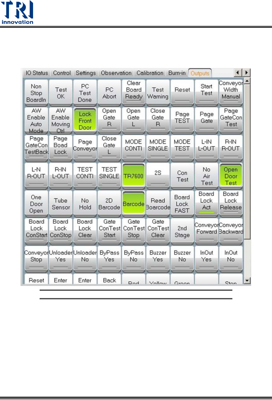
3.9 Output
Users can ignore this section, since only professional TRI engineers will use below
functions.
Figure 20: VPLC – Warning – CONV. WIDTH MOTOR ABNORMAL