TOYO-GTH.pdf - 第27页
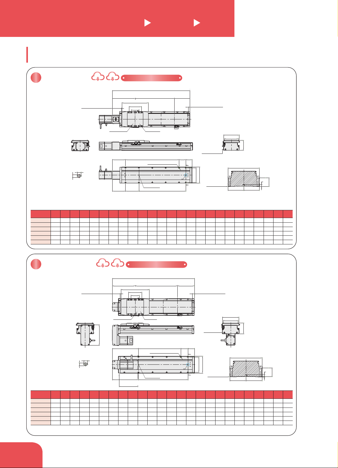
單位 Unit : mm 單位 Unit : mm 60 2-∅6 10H7 8-M6 17 +0.012 6 0 8 B View 滑台原點151 Origin of actuator:151 2-Ø6 7 H7 74.5 M*100 A 46 108 120 119.5 L B 100 ±0.02 P 74.5 C C N-M8 16+∅6.8 THR. 180.75 104 118 76 基準面 The datum…
單位 Unit : mm
單位 Unit : mm
2-Ø67 H7
10H72-∅6
8-M617
145
※馬達總長度需限制於132內。
The overall length of the motor must be within 132 cm.
184.5 M*100 A
46
108
120
B
P184.5
C
C
N-M8 16+∅6.8 THR.
119.5
L
60
95
滑台機械極限13.75±1
Mechanical limit:13.75±1
有效行程
Stroke
滑台原點161
Origin of actuator:161
滑台機械極限55.25±1
Mechanical limit:55.25±1
201.5201.5
104
118
76
基準面
The datum plane
+0.012
6
0
8
B View
C-C View
60±0.03
60
120
32.5
基準面
The datum plane
7
8-M617
2-∅6 10 H7
滑台機械極限13.75±1
Mechanical limit:13.75±1
滑台機械極限68.75±1
Mechanical limit:68.75±1
119.5
L
有效行程 Stroke
滑台原點174.5
Origin of actuator:174.5
95
201.5
60
118
基準面
The datum plane
104
76
N-M816+∅6.8 THR.
C
C
98 M*100 A 46
108
120
98 100±0.02 P
B
2-Ø6 7 H7
C-C View
60±0.03
60
120
32.5
基準面
The datum plane
+0.012
6
0
8
B View
7
有效行程
Stroke
50
※
100 150 200 250 300 350 400 450 500 550 600 650 700 750 800 850 900 950 1000 1050 1100 1150 1200 1250
L 330.5 380.5 430.5 480.5 530.5 580.5 630.5 680.5 730.5 780.5 830.5 880.5 930.5 980.5
1030.5 1080.5 1130.5 1180.5 1230.5 1280.5 1330.5 1380.5 1430.5 1480.5 1530.5
A 100 50 100 50 100 50 100 50 100 50 100 50 100 50 100 50 100 50 100 50 100 50 100 50 100
M 0 1 1 2 2 3 3 4 4 5 5 6 6 7 7 8 8 9 9 10 10 11 11 12 12
N 4 6 6 8 8 10 10 12 12 14 14 16 16 18 18 20 20 22 22 24 24 26 26 28 28
P 100 150 200 250 300 350 400 450 500 550 600 650 700 750 800 850 900 950 1000 1050 1100 1150 1200 1250 1300
KG 5.21 5.56 5.91 6.26 6.61 6.96 7.31 7.66 8.01 8.36 8.71 9.06 9.41 9.76 10.11 10.46 10.81 11.16 11.51 11.86 12.21 12.56 12.91 13.26 13.61
有效行程
Stroke
50
※
100 150 200 250 300 350 400 450 500 550 600 650 700 750 800 850 900 950 1000 1050 1100 1150 1200 1250
L 344 394 444 494 544 594 644 694 744 794 844 894 944 994 1044 1094 1144 1194 1244 1294 1344 1394 1444 1494 1544
A 100 50 100 50 100 50 100 50 100 50 100 50 100 50 100 50 100 50 100 50 100 50 100 50 100
M 1 2 2 3 3 4 4 5 5 6 6 7 7 8 8 9 9 10 10 11 11 12 12 13 13
N 6 8 8 10 10 12 12 14 14 16 16 18 18 20 20 22 22 24 24 26 26 28 28 30 30
P 100 150 200 250 300 350 400 450 500 550 600 650 700 750 800 850 900 950 1000 1050 1100 1150 1200 1250 1300
KG 5.05 5.4 5.75 6.1 6.45 6.8 7.15 7.5 7.85 8.2 8.55 8.9 9.25 9.6 9.95 10.3 10.65 11 11.35 11.7 12.05 12.4 12.75 13.1 13.45
GTH12
單軸 /1-axis
軌道內嵌
Built-in Linear Motion Guide
螺桿驅動
Ball Screw Drive
BC
馬達外露
Motor Exposed
2D CAD 3D CAD
D
ownload CAD data at http://www.toyo.tw
BM
馬達下折
Motor Bottom Side
2D CAD 3D CAD
Download CAD data at http://www.toyo.tw
馬達外露 / 馬達下折
Motor Exposed / Motor Bottom Side
* 馬達下折時,若選用煞車馬達,或是超出馬達總長度限制時無法套用標準 PIN 孔,如有需求請洽我司業務。
When motor with brake assembled on lower side, or the total length over than spec limit, it may not use standard pinhole. Please contact our sales department if you need more information & requirement.
※行程 50 時 , 因本
體上鎖式固定孔會被
滑座遮住,僅能使用
4 支螺絲固定,建議
客戶本體使用下鎖式
固定孔鎖附。
When the stroke is 50mm,
if fixing the body from
the top to the bottom, the
xing hole will be blocked
by slider and only can be
uses 4 screws to x;as a
result, suggest that xing
actuator body from the
bottom to the top.
※行程 50 時 , 因本
體上鎖式固定孔會被
滑座遮住,僅能使用
4 支螺絲固定,建議
客戶本體使用下鎖式
固定孔鎖附。
When the stroke is 50mm,
if fixing the body from
the top to the bottom, the
xing hole will be blocked
by slider and only can be
uses 4 screws to x;as a
result, suggest that xing
actuator body from the
bottom to the top.
109
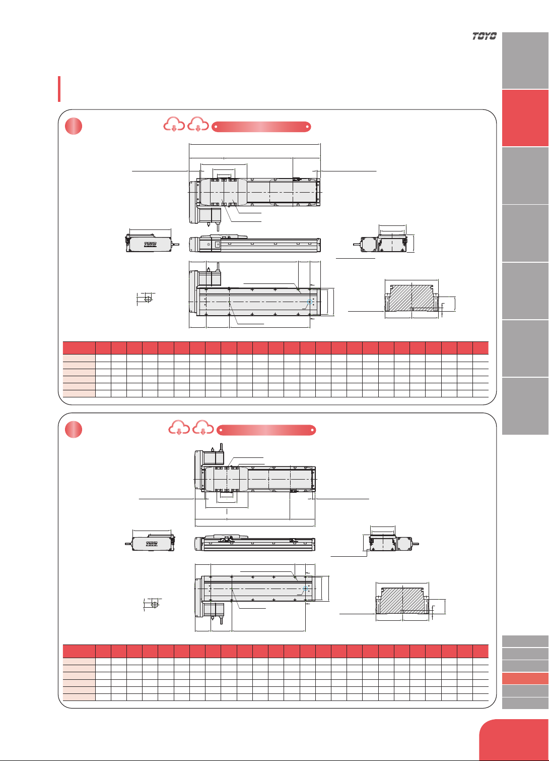
單位 Unit : mm
單位 Unit : mm
60
2-∅610H7
8-M6 17
+0.012
6
0
8
B View
滑台原點151
Origin of actuator:151
2-Ø6
7 H7
74.5 M*100 A 46
108
120
119.5
L
B
100±0.02 P74.5
C
C
N-M8 16+∅6.8 THR.
180.75
104
118
76
基準面
The datum plane
滑台機械極限13.75±1
Mechanical limit:13.75±1
有效行程 Stroke
滑台機械極限45.25±1
Mechanical limit:45.25±1
95
201.5
C-C View
60±0.03
60
120
32.5
基準面
The datum plane
7
2-∅610H7
+0.012
6
0
8
B View
滑台機械極限45.25±1
Mechanical limit:45.25±1
滑台機械極限13.75±1
Mechanical limit:13.75±1
119.5
L
60
95
201.5
74.5 M*100 A 46
108
120
B
100±0.02 P74.5
8-M6
C
C
2-Ø67 H7
N-M8 16+∅6.8 THR.
180.75
有效行程 Stroke
滑台原點151
Origin of actuator:151
104
118
76
基準面
The datum plane
C-C View
60±0.03
60
120
32.5
基準面
The datum plane
7
有效行程
Stroke
50
※
100 150 200 250 300 350 400 450 500 550 600 650 700 750 800 850 900 950 1000 1050 1100 1150 1200 1250
L 320.5 370.5 420.5 470.5 520.5 570.5 620.5 670.5 720.5 770.5 820.5 870.5 920.5 970.5
1020.5 1070.5 1120.5 1170.5 1220.5 1270.5 1320.5 1370.5 1420.5 1470.5 1520.5
A 100 50 100 50 100 50 100 50 100 50 100 50 100 50 100 50 100 50 100 50 100 50 100 50 100
M 1 2 2 3 3 4 4 5 5 6 6 7 7 8 8 9 9 10 10 11 11 12 12 13 13
N 6 8 8 10 10 12 12 14 14 16 16 18 18 20 20 22 22 24 24 26 26 28 28 30 30
P 100 150 200 250 300 350 400 450 500 550 600 650 700 750 800 850 900 950 1000 1050 1100 1150 1200 1250 1300
KG 5.25 5.6 5.95 6.3 6.65 7 7.35 7.7 8.05 8.4 8.75 9.1 9.45 9.8 10.15 10.85 11.2 11.55 11.9 12.25 12.6 12.56 12.91 13.26 13.61
BL
馬達左折
Motor Left Side
2D CAD 3D CAD
D
ownload CAD data at http://www.toyo.tw
BR
馬達右折
Motor Right Side
2D CAD 3D CAD
D
ownload CAD data at http://www.toyo.tw
馬達左折 / 馬達右折
Motor Left Side / Motor Right Side
※行程 50 時 , 因本
體上鎖式固定孔會被
滑座遮住,僅能使用
4 支螺絲固定,建議
客戶本體使用下鎖式
固定孔鎖附。
When the stroke is 50mm,
if fixing the body from
the top to the bottom, the
xing hole will be blocked
by slider and only can be
uses 4 screws to x;as a
result, suggest that xing
actuator body from the
bottom to the top.
※行程 50 時 , 因本
體上鎖式固定孔會被
滑座遮住,僅能使用
4 支螺絲固定,建議
客戶本體使用下鎖式
固定孔鎖附。
When the stroke is 50mm,
if fixing the body from
the top to the bottom, the
xing hole will be blocked
by slider and only can be
uses 4 screws to x;as a
result, suggest that xing
actuator body from the
bottom to the top.
http://www.toyo.tw
110
應用例
Application
一般 / 皮帶仕樣
ETB / M
無塵 / 螺桿仕樣
GCH / ECH
無塵 / 皮帶仕樣
ECB
直交連結
XYGT / XYTH / XYTB
參考資料
Reference
單軸
1 axis
GTH
一般 / 螺桿仕樣
GTH Series
GTH8S
GTH8
GTH12
GTH5S
GTH5
GTH4
GTH8S
GTH8
GTH12
GTH5S
GTH5
GTH4
型號表示方式
Ordering Method
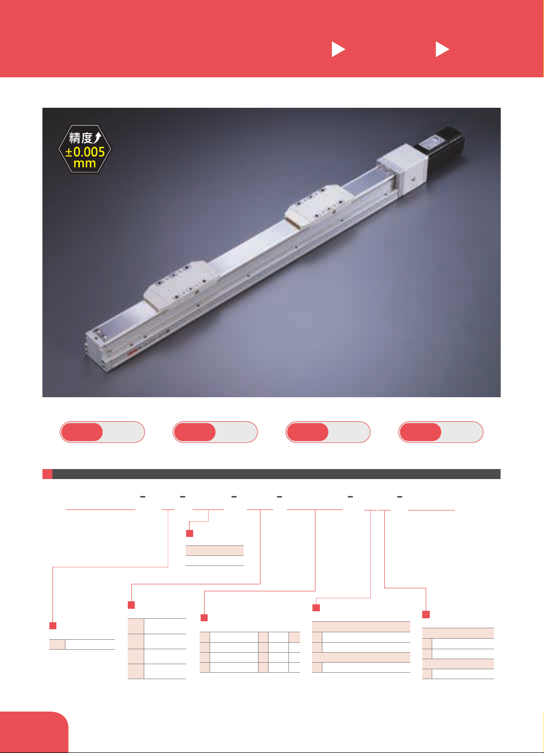
GTH5S 單軸 /1-axis
軌道內嵌
Built-in Linear Motion Guide
螺桿驅動
Ball Screw Drive
最大行程
Maximum Stroke
325mm
最高速度
Maximum Speed
100mm/s
馬達容量
Motor output
100W
滾珠螺桿
Ball Screw
ø
12mm
此圖僅供參考,出貨規格詳見尺寸圖面
The picture is just for the reference. Please check the the actual dimensions on the drawing.
L2 BC
GTH5S M10B C4 0001
本體型號
Model
行程
Stroke
特注式樣
Special Order No.
間隔25 25 mm Pitch
25-325mm
Home Sensor
原點感應器
外掛型 Out Side
馬達側 Motor Side
反馬達側 Opposite Motor Side
無
No Sensor
無
No Sensor
C
D
E
SENSOR
SENSOR
Limit Sensor
端點極限感應器
外掛型 Out Side
1只
1 Pc
2 Pc
2只
無
No Sensor
無
No Sensor
3
4
5
SENSOR
SENSOR
Motor Brand、Power Output
馬達廠牌、功率
05
-
B
100W
-
-
10
20
40
三菱
Mitsubishi
Y
國際
Panasonic
M
安川 Yaskawa
T
台達
Delta
P
*若無煞車則不表示。
*If No Brake,No Description.
馬達位置
Motor Position
BC
BM
BL
BR
馬達外露
馬達下折
馬達左折
馬達右折
Motor Exposed
Motor Right Side
Motor Left Side
Motor Bottom Side
螺桿導程
Ball Screw Lead
2 2mm
*反向同動只能對應導程2
100
Dual carriage synchronous movement
in reverse direction can only fit at lead
of 2mm.
When the stroke is 25 / 50 / 75mm the sensor installation
has the following restrictions:
*選擇行程25/50/75時,有以下限制:
1. 原點與極限需放置於不同側。
Home sensor and limit sensor has to be installed on the
different side of body.
2. 滑座左右兩側皆需安裝感應片。
Both sides of slider need to install the sensor trigger device.
111