E4000-90023+N67xx+dut+ps+installation.pdf.pdf - 第13页
N67xx DUT Power Supply Installation 1-9 Connecting to the ASRU Card Connecting to Channel s 1 through 4 The N6751 is a 4-output DUT power supply. One ASRU channel is r equir ed for each output. 1 Locate the highest numbe…

1-8 N67xx DUT Power Supply Installation
Table 1-3 Connector B to J9 on ASRU Card
Pin Wire Color Wire Size Con/Terminal
1NC
2NC
3NC
4NC
5GRN 24 K1
6WHT 24 K4
7WHT/BRN20
8WHT/BRN20
9WHT/BLK 20
10 WHT/BLK 20
11 NC
12 NC
13 BLU 24 L1
14 WHT 24 L4
15 WHT/ORN 20
16 WHT/ORN 20
17 WHT/RED 20
18 WHT/RED 20
19 NC
20 NC
K3
K2
L3
L2
N67xx DUT Power Supply Installation 1-9
Connecting to the ASRU Card
Connecting to Channels 1 through 4
The N6751 is a 4-output DUT power supply. One ASRU channel is required for each
output.
1 Locate the highest numbered module with channels 1 through 4 available on
the ASRU Card.
If channels 1 through 4 are not available, see Connecting to Channels 5 and 6
on page 1-10.
2 Connect the DUT Power Supply cable to the ASRU Card and to the N6751
power supply, as illustrated in Figure 1-5.
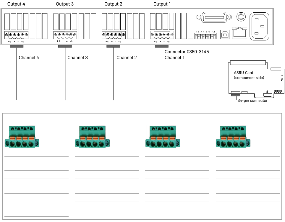
Figure 1-5 N6751 output connections – Channels 1 through 4
Channel 4 Channel 3 Channel 2 Channel 1
P/S Label on
cable
Cable color P/S Label on
cable
Cable color P/S Label on
cable
Cable color P/S Label on
cable
Cable color
+S F1 GRN +S G1 BLU +S H1 RED +S J1 BLK
+ F2 RED
RED/WHT
+ G2 BLU/WHT + H2 RED/WHT + J2 BLK/WHT
– G3 GRN/WHT – H3 ORN/WHT – J3 BRN/WHT
– F3 BLK
BLK/WHT
–S G4 WHT –S H4 WHT –S J4 WHT
–S F4 WHT
F1 F2 F3 F4
G1 G2 G3 G4
H1 H2 H3 H4
J1 J2 J3 J4
1-10 N67xx DUT Power Supply Installation
Connecting to Channels 5 and 6
If channels 1 through 4 are not available in any module, cable the N6751 supply to
a bank where both modules have channels 5 and 6 available. Split the outputs as
shown in Figure 1-6. Notice that output 3 goes to channel 5 and output 4 goes to
channel 6 on the ASRU Card in the higher numbered module. It is possible that
there will not be enough ASRU Card channels available to use all of the power
supply outputs. Output 1 goes to channel 5 and output 2 goes to channel 6 on the
ASRU Card in the lower numbered module in the same bank.
To connect all of the outputs, two cables are necessary since the outputs will go to
two modules. Remember to connect the banana plug ground on the back of the
power supply and the ground lug connector to the ASRU Card.
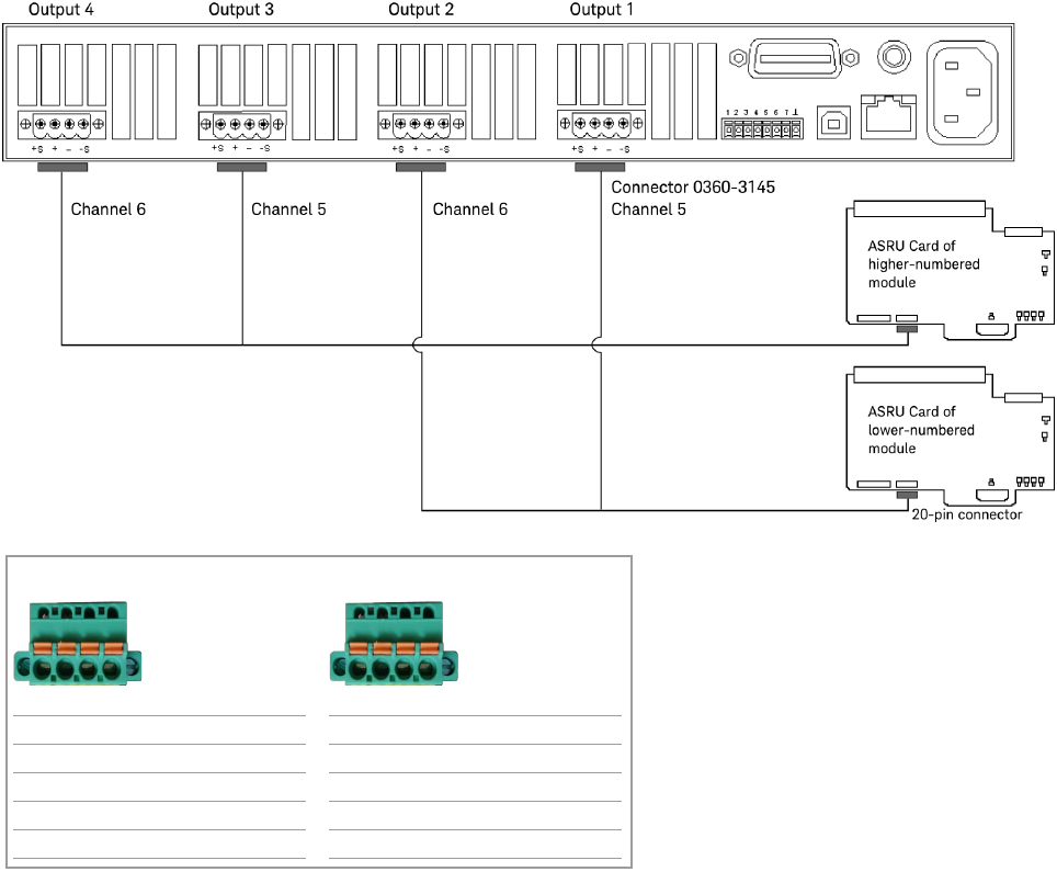
Figure 1-6 Alternative N6751 output connections – Channels 5 and 6
Channel 6 Channel 5
P/S Label on cable Cable color P/S Label on cable Cable color
+S L1 BLU +S K1 GRN
+ L2 RED/WHT + K2 BLK/WHT
– L3 ORN/WHT – K3 BRN/WHT
–S L4 WHT –S K4 WHT
L1 L2 L3 L4
K1 K2 K3 K4