E4000-90023+N67xx+dut+ps+installation.pdf.pdf - 第36页
2-2 N67xx DUT Power Supply Installation Replacing a Power Module Tool s requir ed • T10 Torx driver • Smal l flat-bla de scr e wdriver 1 Remove the blower cover: a Remove the sc r ews fr om the top and si des of the blow…

2-2 N67xx DUT Power Supply Installation
Replacing a Power Module
Tools required
• T10 Torx driver
• Small flat-blade screwdriver
1 Remove the blower cover:
a Remove the screws from the top and sides of the blower cover.
b Tilt the cover up and slide it out.
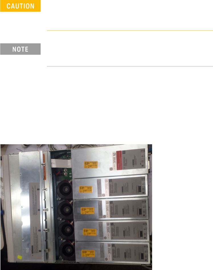
2 Use a Torx driver to remove the screws at each end of the power module and
remove it from the frame.
Turn the DUT power supply off and disconnect the power
cable before removing and installing power modules.
Observe all standard electrostatic discharge precautions
before handling electronic components.
Always replace a power module with the same model,
otherwise the DUT power supply cannot be controlled by the
i3070 In-Circuit Test Software.
N67xx DUT Power Supply Installation 2-3
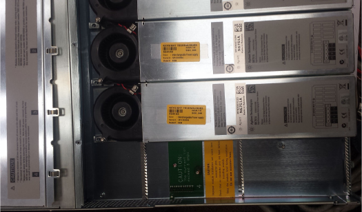
3 Align the new power module over the pins and push it down onto the
connector.
4 Secure with the screws at each end of the power module. Because the RFI
strips apply upward pressure, continue pushing down on the module until the
screws are tight.
5 Replace the blower cover. Carefully fit the spring clips under the lip of the
power modules.