E4000-90023+N67xx+dut+ps+installation.pdf.pdf - 第38页
2-4 N67xx DUT Power Supply Installation Replacing Connectors on Old Output Cables The output cables fr om some older i3070 systems can be used with the N67xx DUT power supplies by cutt ing off the lugs and r ewiring them…
N67xx DUT Power Supply Installation 2-3
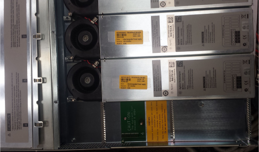
3 Align the new power module over the pins and push it down onto the
connector.
4 Secure with the screws at each end of the power module. Because the RFI
strips apply upward pressure, continue pushing down on the module until the
screws are tight.
5 Replace the blower cover. Carefully fit the spring clips under the lip of the
power modules.
2-4 N67xx DUT Power Supply Installation
Replacing Connectors on Old Output Cables
The output cables from some older i3070 systems can be used with the N67xx DUT
power supplies by cutting off the lugs and rewiring them based on the diagrams in
Connecting the Output Cables.
Note that the labels on new output cables are different from the old cables, and the
wiring information in this chapter refer to the new labels. Table 2-1 refers you to the
correct tables for the mapping of old to new labels, depending on the output cable
and channel you are using.
Table 2-1
Refer to: Cable Channel
Table 2-2 E4000-61602 for 4-module system Channels 1–4
E1170-61607 2-module system Channels 1–4
E1170-61606 for 2-module system Channels 5–6
Table 2-3 E4000-61606 for 2-module system Channels 5–6
Table 2-4 E4000-61602 for 4-module system Channels 5–6
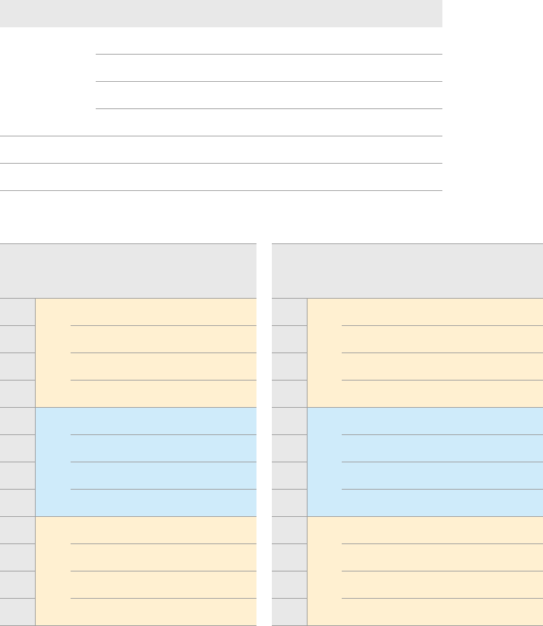
Table 2-2 Mapping old and new labels on output cables
Label on Cable: Label on Cable:
P/S Old New Cable Color P/S Old New Cable Color
+S 5 J1 BLK +S 5 H1 RED
+ 8 J2 BLK/WHT + 8 H2 RED/WHT
– 7 J3 BRN/WHT – 7 H3 ORN/WHT
–S 6 J4 WHT –S 6 H4 WHT
+S 1 G1 BLU +S 1 F1 GRN
+ 4 G2 BLU/WHT + 4 F2 RED, RED/WHT
– 3 G3 GRN/WHT – 3 F3 BLK, BLK/WHT
–S 2 G4 WHT –S 2 F4 WHT
+S 1 K1 GRN +S 5 L1 BLU
+ 4 K2 BLK/WHT + 8 L2 RED/WHT
– 3 K3 BRN/WHT – 7 L3 ORN/WHT
–S 2 K4 WHT –S 6 L4 WHT
Channel 1
Channel 2
Channel 3
Channel 4
Channel 5
Channel 6
N67xx DUT Power Supply Installation 2-5
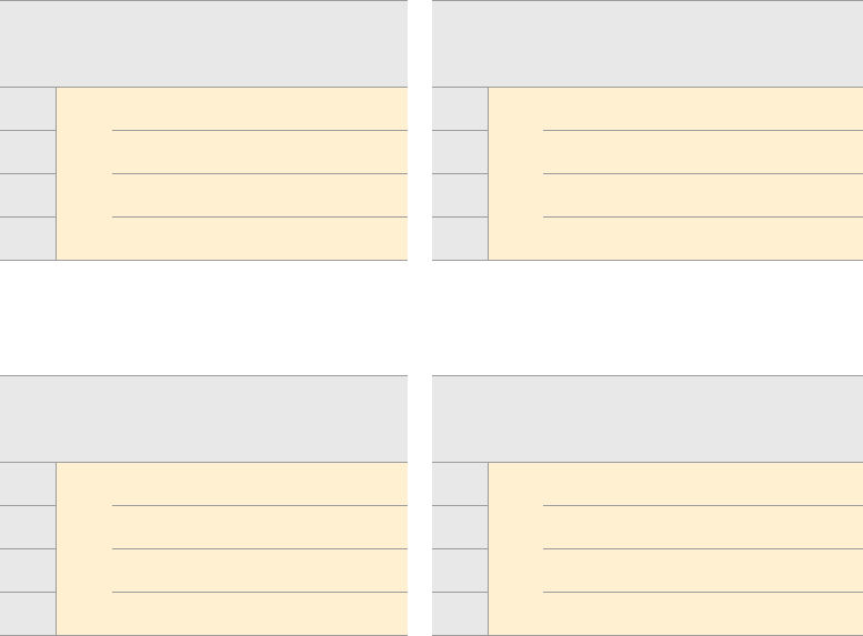
Table 2-3 Mapping old and new labels on output cables
(E4000-61606, 2-module)
Label on Cable: Label on Cable:
P/S Old New Cable Color P/S Old New Cable Color
+S 1 K1 GRN +S 5 L1 BLU
+ 4 K2 BLK/RED + 8 L2 RED/BLK
– 3 K3 BRN/RED – 7 L3 ORN/WHT
–S 2 K4 WHT –S 6 L4 WHT
Table 2-4 Mapping old and new labels on output cables
(E4000-61602, 4-module)
Label on Cable: Label on Cable:
P/S Old New Cable Color P/S Old New Cable Color
+S 1 K1 GRN +S 5 L1 BLU
+ 4 K2 BRN/BLK + 8 L2 BRN/BLK
– 3 K3 BRN – 7 L3 ORN
–S 2 K4 WHT –S 6 L4 WHT
Channel 5
Channel 6
Channel 5
Channel 6