E4000-90023+N67xx+dut+ps+installation.pdf.pdf - 第28页
1-24 N67xx DUT Power Supply Installation From the fr ont panel: 1 Selec t Protect / Clear . 2 Select the Clear button. Using SCPI command: To clear a pr otection fa ul t on output1, execute OUTP:PROT:CLE(@1 )
N67xx DUT Power Supply Installation 1-23
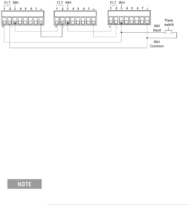
Fault/Inhibit System Protection
The following figure illustrates some ways that you can connect the Fault/Inhibit
pins of the connector.
As shown above, when the Fault outputs and Inhibit inputs of several DUT power
supplies are daisy-chained, an internal fault condition in one of the DUT power
supplies will disable all of them without intervention by either the controller or
external circuitry.
You can also connect the Inhibit input to a manual switch or external control signal
that will short the Inhibit pin to common whenever it is necessary to disable all
output channels in the DUT power supply. Negative polarity must be programmed
for all pins in this case. You can also use the Fault output to drive an external relay
circuit or signal other devices whenever a user-definable fault occurs.
Clearing a System Protection Fault
If an over-voltage, over-current, over-temperature, power-fail condition,
power-limit condition, protection condition, or inhibit signal occurs, the power
system turns off the affected output channel. The appropriate operating status
indicator on the front panel will be on.
To clear the protection function and restore normal operation, first remove that
condition that caused the protection fault. Then, clear the protection function.
To clear the daisy-chained fault signal if the operating mode of the Inhibit input is
Live, simply clear the output protection on any ONE DUT power supply as described
below. If the operating mode of the Inhibit input is Latched, turn off the Inhibit input
on ALL DUT power supplies individually. To re-enable the chain, re-program the
Inhibit input on each DUT power supply to Latched mode.
Even when the initial fault condition or external signal is
removed, the Inhibit fault signal is still active and will
continue to shut down the outputs of all the DUT power
supplies.
1-24 N67xx DUT Power Supply Installation
From the front panel:
1 Select Protect/Clear.
2 Select the Clear button.
Using SCPI command:
To clear a protection fault on output1, execute OUTP:PROT:CLE(@1)
N67xx DUT Power Supply Installation 1-25
Connecting the Power and GPIB Cables
Plug the DUT Power Supply’s power cord into the nearest power outlet box, with
the proper voltage, in the testhead. Each outlet box is marked with its voltage.
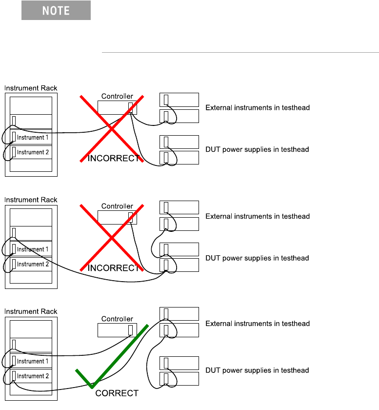
Connect 0.5-meter GPIB cables (10833D) to existing supplies. The DUT power
supplies handshake faster than most other devices on the bus. If they are cabled
directly to the controller, the glitches they generate can cause GPIB timeout errors.
Figure 1-13 Connecting the GPIB cables
The DUT Power Supply GPIB cables must be at the end of
the GPIB cable string. Figure 1-13 shows how to connect
the GPIB cables, including when an optional instrument bay
is used.