E4000-90023+N67xx+dut+ps+installation.pdf.pdf - 第30页
1-26 N67xx DUT Power Supply Installation Pr ogramming the GPIB Ad dress on Power Suppl ies Ta b l e 1 - 8 shows the valid GPIB addr esses for DUT powe r supplies. Be sur e not to duplicate a GPIB addr ess if maki ng chan…
N67xx DUT Power Supply Installation 1-25
Connecting the Power and GPIB Cables
Plug the DUT Power Supply’s power cord into the nearest power outlet box, with
the proper voltage, in the testhead. Each outlet box is marked with its voltage.
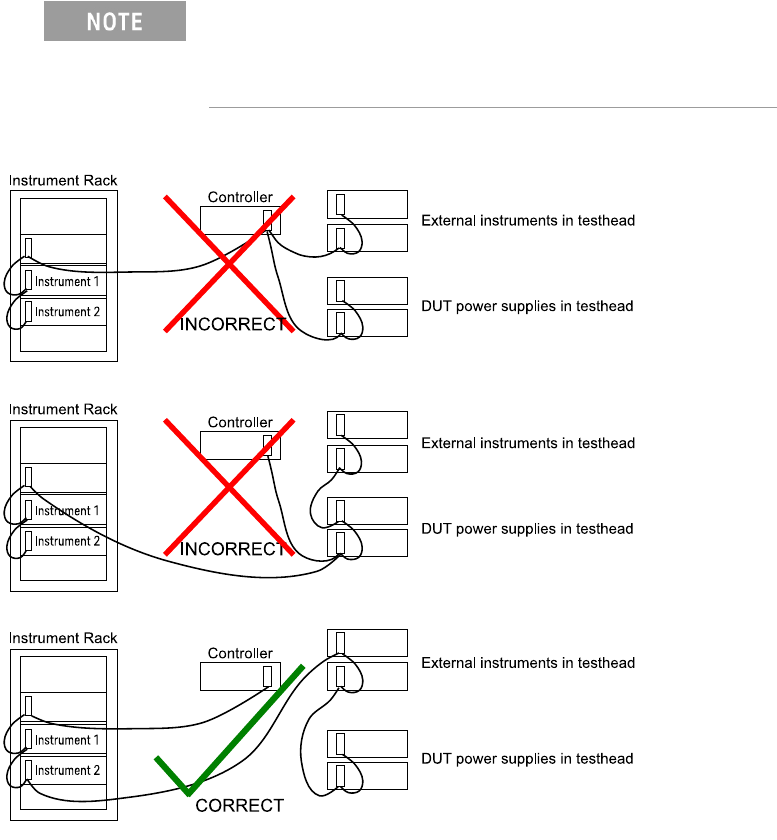
Connect 0.5-meter GPIB cables (10833D) to existing supplies. The DUT power
supplies handshake faster than most other devices on the bus. If they are cabled
directly to the controller, the glitches they generate can cause GPIB timeout errors.
Figure 1-13 Connecting the GPIB cables
The DUT Power Supply GPIB cables must be at the end of
the GPIB cable string. Figure 1-13 shows how to connect
the GPIB cables, including when an optional instrument bay
is used.

1-26 N67xx DUT Power Supply Installation
Programming the GPIB Address on Power Supplies
Table 1-8 shows the valid GPIB addresses for DUT power supplies. Be sure not to
duplicate a GPIB address if making changes.
Set the GPIB address from the front panel of the DUT power supply.
1 Press ADDR and enter the address.
2 Press ENTER.
Table 1-8 DUT Power Supply Addressing
Power Supply Connection GPIB Address Device File (in /dev/)
Module 0, ASRU Card channels 1-4
Module 0, ASRU Card channels 1, 2, 5, 6
22 ps0
Module 1, ASRU Card channels 1-4
Module 1, ASRU Card channels 1, 2, 5, 6
23 ps1
Module 2, ASRU Card channels 1-4
Module 2, ASRU Card channels 1, 2, 5, 6
24 ps2
Module 3, ASRU Card channels 1-4
Module 3, ASRU Card channels 1, 2, 5, 6
25 ps3
Module 0, ASRU Card channel 5 or 5-6 26 ps4
Module 0, ASRU Card channel 6 27 ps5
Module 1, ASRU Card channels 5-6 28 ps6
Module 1, ASRU Card channel 6 29 ps7
Module 2, ASRU Card channels 5-6 1 ps8
Module 2, ASRU Card channel 6 2 ps9
Module 3, ASRU Card channels 5-6 3 ps10
Module 3, ASRU Card channel 6 4 ps11
Module 0, ASRU Card channel 3 12 ps20
Module 0, ASRU Card channel 4 13 ps21
Module 1, ASRU Card channel 3 15 ps22
Module 1, ASRU Card channel 4 16 ps23
Module 2, ASRU Card channel 3 18 ps24
Module 2, ASRU Card channel 4 19 ps25
Module 3, ASRU Card channel 3 20 ps26
Module 3, ASRU Card channel 4 30 ps27
N67xx DUT Power Supply Installation 1-27
Module 0, Utility Card channel 7 or 7-8 12 ps12
Module 0, Utility Card channel 8 13 ps13
Module 1, Utility Card channel 7 or 7-8 15 ps14
Module 1, Utility Card channel 8 16 ps15
Module 2, Utility Card channel 7 or 7-8 18 ps16
Module 2, Utility Card channel 8 19 ps17
Module 3, Utility Card channel 7 or 7-8 20 ps18
Module 3, Utility Card channel 8 30 ps19
If a supply is split between two modules, use the device file
address and GPIB address of the lower numbered module.
Table 1-8 DUT Power Supply Addressing (continued)
Power Supply Connection GPIB Address Device File (in /dev/)