E4000-90023+N67xx+dut+ps+installation.pdf.pdf - 第35页
Keysight i3070 In-Circuit Test System N67xx DUT Power Supply Installation Replacement Procedures Replacing a Power Module 2-2 Replacing Connectors on Old Output Cables 2-4

1-30 N67xx DUT Power Supply Installation
Verifying Operation
1 Look at the Testhead Config screen and verify that the official configuration
agrees with the actual configuration.
2 Run Diagnostics, especially the DUT power supply tests, with a pin verification
fixture.
In Case of Difficulty
If you need phone support, go to www.keysight.com/find/contactus for contact
information.
If Diagnostics fails, verify that there are no shorting straps on
the terminals. Some supplies come from the factory with
shorting straps. They must be removed to do remote sensing.

2-2 N67xx DUT Power Supply Installation
Replacing a Power Module
Tools required
• T10 Torx driver
• Small flat-blade screwdriver
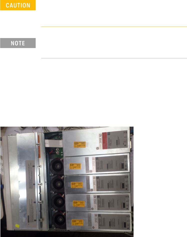
1 Remove the blower cover:
a Remove the screws from the top and sides of the blower cover.
b Tilt the cover up and slide it out.
2 Use a Torx driver to remove the screws at each end of the power module and
remove it from the frame.
Turn the DUT power supply off and disconnect the power
cable before removing and installing power modules.
Observe all standard electrostatic discharge precautions
before handling electronic components.
Always replace a power module with the same model,
otherwise the DUT power supply cannot be controlled by the
i3070 In-Circuit Test Software.