manual-ale-automatic-feed-soldering-control-unit-jbc-0033469_ID-245046_EN.pdf - 第11页
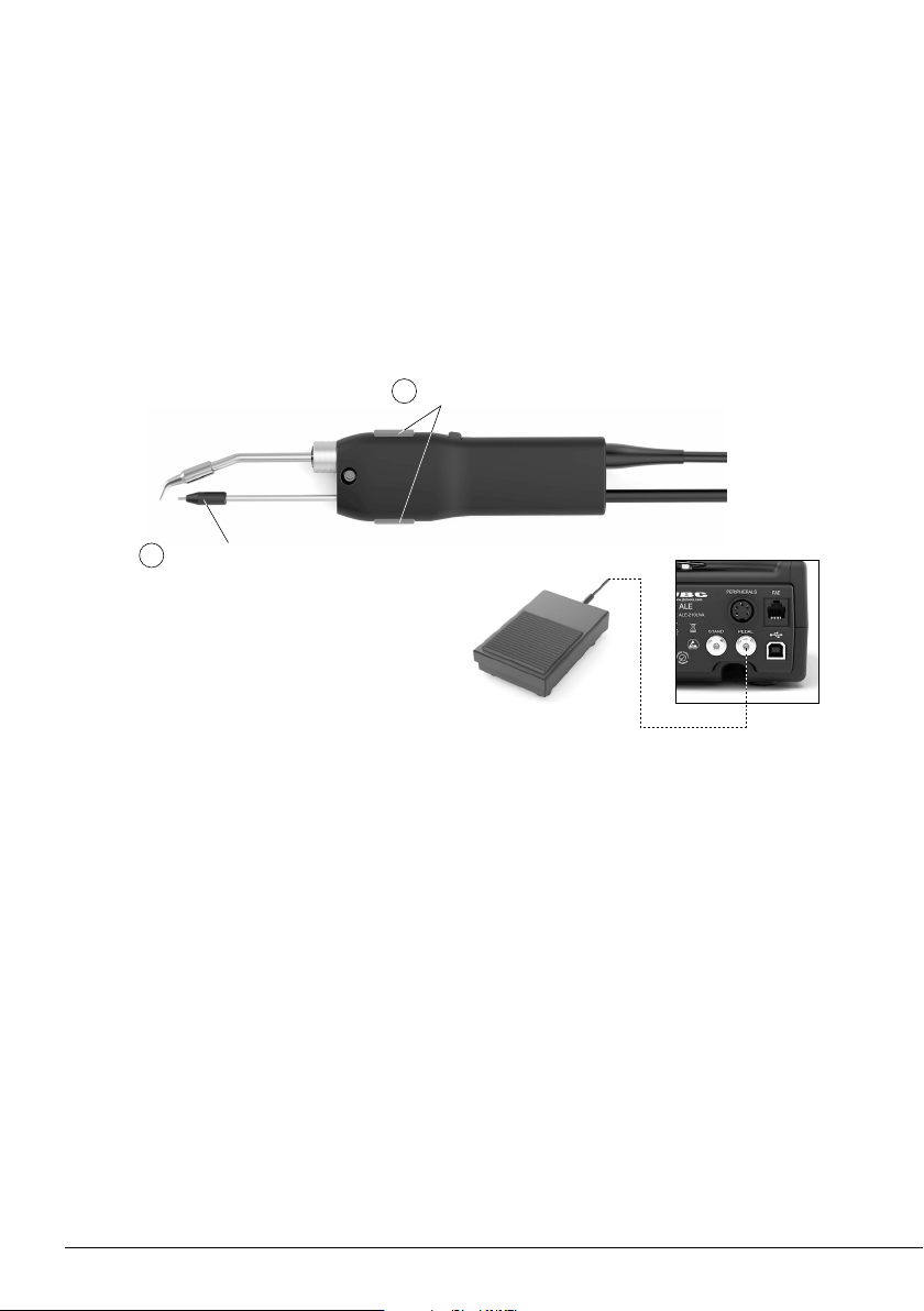
2 1 D ra g g in g B u t t on s O u t l e t N o z zle Forwar d the solder wir e pushing any of the two dragging buttons (1) until the wir e comes out of the outlet nozzle (2). Mor e convenient handling thanks to its two d…
2
1
Dragging Buttons
Outlet Nozzle
Forward the solder wire pushing any of the two dragging buttons (1) until the wire comes out of the
outlet nozzle (2).
More convenient handling thanks to its two dragging buttons
The component layout or application angle may require working in different positions. Having one button
on each side of the tool increases adaptability and makes it easier to reach diffi cult solder joints without
compromising user comfort.
Solder Wire Feeding
Alternatively, solder wire can also be fed using
pedal P405. The pedal should be plugged in at
the rear of the feeder control unit into the pedal
connector.
EARTH FUSE F1.25 A
USE ONLY WITH A 250 V FUSE
EARTH FUSE F1.25 A
EARTH FUSE F1.25 A
USE ONLY WITH A 250 V FUSE
EARTH FUSE F1.25 A
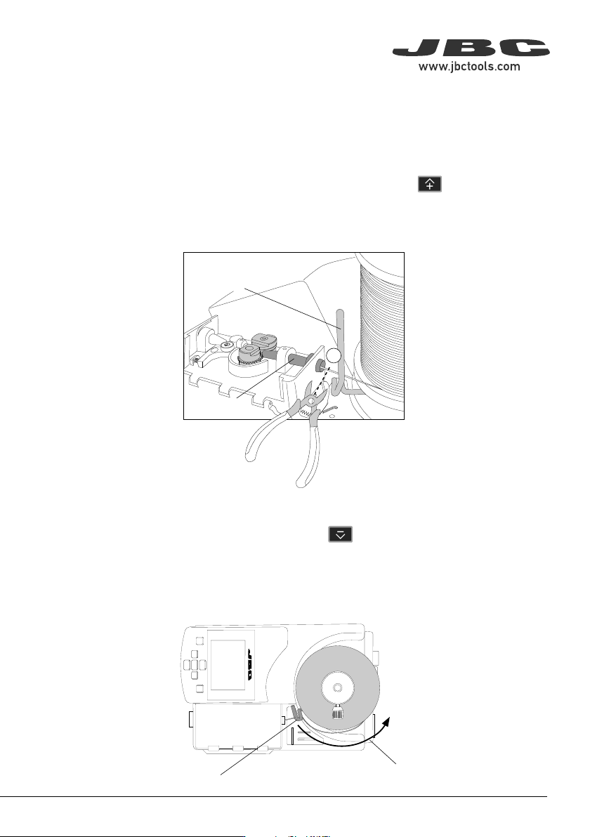
Inlet Nozzle
Wire Guidance
1
Solder Wire
Wire Winding Direction
Solder Wire Unloading
With Solder Wire Perforation
To unload solder wire with perforation that has already passed through the guide tube, cut the wire
between the wire guidance and the inlet nozzle (1).
To extract the wire out of the tube, hold the tool on your hand and press until the wire stops
moving forward.
Grasp the wire coming out of the outlet nozzle with a pliers and pull from it until it is completely out.
Without Solder Wire Perforation
When using a kit without solder wire perforation, press until the wire is completely wound to
unload the solder wire. It is best to rotate the reel by hand as the wire is being pulled back in order
to keep it neatly arranged on the reel.
Or, If preferred, proceed as described before for perforated solder wire unloading.
10
2
1
Dragging Buttons
Outlet Nozzle
Forward the solder wire pushing any of the two dragging buttons (1) until the wire comes out of the
outlet nozzle (2).
More convenient handling thanks to its two dragging buttons
The component layout or application angle may require working in different positions. Having one button
on each side of the tool increases adaptability and makes it easier to reach diffi cult solder joints without
compromising user comfort.
Solder Wire Feeding
Alternatively, solder wire can also be fed using
pedal P405. The pedal should be plugged in at
the rear of the feeder control unit into the pedal
connector.
EARTH FUSE F1.25 A
USE ONLY WITH A 250 V FUSE
EARTH FUSE F1.25 A
EARTH FUSE F1.25 A
USE ONLY WITH A 250 V FUSE
EARTH FUSE F1.25 A
Inlet Nozzle
Wire Guidance
1
Solder Wire
Wire Winding Direction
Solder Wire Unloading
With Solder Wire Perforation
To unload solder wire with perforation that has already passed through the guide tube, cut the wire
between the wire guidance and the inlet nozzle (1).
To extract the wire out of the tube, hold the tool on your hand and press until the wire stops
moving forward.
Grasp the wire coming out of the outlet nozzle with a pliers and pull from it until it is completely out.
Without Solder Wire Perforation
When using a kit without solder wire perforation, press until the wire is completely wound to
unload the solder wire. It is best to rotate the reel by hand as the wire is being pulled back in order
to keep it neatly arranged on the reel.
Or, If preferred, proceed as described before for perforated solder wire unloading.
11
40 mm
50 mm
60 mm
80 mm
100 mm
130 mm
130 mm
para manuales - negro plano
200 mm
300 mm
EARTH FUSE F1.25 A
USE ONLY WITH A 250 V FUSE
EARTH FUSE F1.25 A
EARTH FUSE F1.25 A
USE ONLY WITH A 250 V FUSE
EARTH FUSE F1.25 A
SFR-B
GSFR
TRA
CLR
EXTRACCIÓN
22220
EXTRACCIÓN
26842
26843
EXTRACCIÓN
26846
26847
26848
EXTRACCIÓN
26844
VERMELL
NEGRE GROC
VERMELL
BLAU
VERMELL
BLAU
BLAU
VERD
VERMELL
BLAU
VERD
VERMELL
NEGRE GROC
VERMELL
BLAU
BLAU
VERD
6
2
3
4
5
1
9
10
12
Guide Tube
Set
*
1
Guide wheel bears diameter marking.
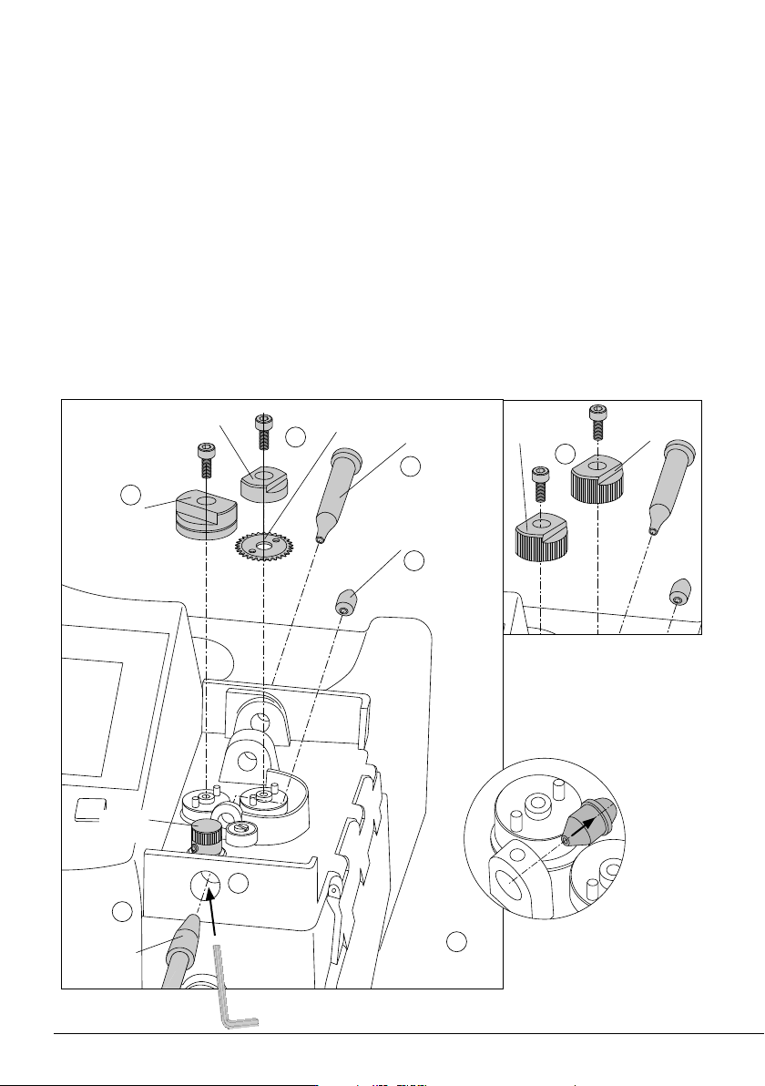
Guide Kits Disassembly
For this operation, disconnect the device from the mains. Unload any solder wire running inside the
guide tube, disconnect the tool from the control unit and open its cover.
Before trying to remove any components, be sure to loosen the corresponding set screws. To do
this, use the Allen key and spanner provided with the station.
First disassemble the guide tube set (1), the guide wheel (4), blade and blade clamp (5) and then the
nozzles (2) + (3). Note: The wheel components
*3
on devices without solder wire perforation (10) are
slightly different from those with solder wire perforation.
Lastly, disassemble the counter wheel (6), introducing the Allen key through the frontal opening (9)
to loosen its set screw.
Inlet
Nozzle
Interm. Nozzle*
2
Blade
Blade Clamp
Guide Wheel*
1
Counter
Wheel
*
2
Intermediate nozzle
disassembly
Support
Wheel*
3
Traction
Wheel*
3
*
3
Wheel components for devices
without solder wire perforation.