manual-ale-automatic-feed-soldering-control-unit-jbc-0033469_ID-245046_EN.pdf - 第15页
ALE250 ALE250 ALE250 ALE250 ALE250 ALE250 ALE250 ALE250 ALE250 ALE250 ALE250 ALE250 ALE250 ALE250 ALE250 6 1 2 3 4 5 7 15 40 mm 50 mm 60 mm 80 mm 100 mm 130 mm 130 mm par a manuales - neg r o plano 200 mm 300 mm Place a …
EARTH FUSE F1.25 A
USE ONLY WITH A 250 V FUSE
EARTH FUSE F1.25 A
SFR-B
GSFR
TRA
CLR
EXTRACCIÓN
22220
EXTRACCIÓN
26842
26843
EXTRACCIÓN
26846
26847
26848
EXTRACCIÓN
26844
VERMELL
NEGRE GROC
VERMELL
BLAU
VERMELL
BLAU
BLAU
VERD
VERMELL
BLAU
VERD
VERMELL
NEGRE GROC
VERMELL
BLAU
BLAU
VERD
2
3
4
5
1
6
14
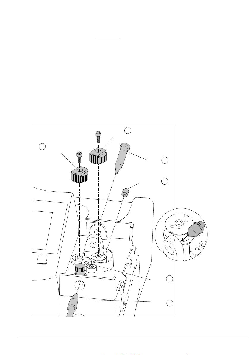
Assemble first the counter wheel (1) in the same way as shown on the previous page (see (1), (2) and
(3) on the page before).
Afterwardas insert the intermediate nozzle (2) until its collar rests against the housing and tighten
its screw.
Assemble the inlet nozzle (3).
Assemble the support wheel* (4) and the traction wheel (5) on the corresponding axis and tighten
the respective screws
Finally insert the guide tube set (6) and tighten the screw.
Support
Wheel *
1
Traction
Wheel
Interm.
Nozzle*
2
Inlet
Nozzle
Counter
Wheel
Guide
Tube Set
*
1
Support wheel bears diameter marking.
*
2
Intermediate nozzle
assembly
Guide Kits Assembly - without Solder Wire Perforation:
ALE250
ALE250
ALE250
ALE250
ALE250
ALE250
ALE250
ALE250
ALE250
ALE250
ALE250
ALE250
ALE250
ALE250
ALE250
6
1
2
3
4
5
7
15
40 mm
50 mm
60 mm
80 mm
100 mm
130 mm
130 mm
para manuales - negro plano
200 mm
300 mm
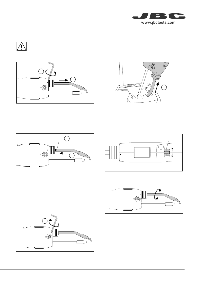
Place a new cartridge into the automatic-feed
iron (4).
Important: It is essential to insert the cartridge
up to the mark for a good connection (5).
2. Removing
1. Unlocking
Loosen the cartridge fixing screw (1) to release
the cartridge (2).
Place the cartridge in the cartridge exchanger
and pull the tool to remove the cartridge (3).
3. Inserting
Changing Cartridges
For a safe cartridge change, unplug the tool or turn off the station before following these guidelines
and wait for the equipment to cool down.
Mark
4. Adjusting
The alignment of the cartridge with the outlet
nozzle (6) can be precisely adjusted by using
the upper tab (7). Make sure the tab is set in
the middle when inserting the cartridge to allow
room for movement to both sides.
5. Fixing
Finally, tighten the cartridge fixing screw to fix the
cartridge in place.
Tab
Flux can cause clogging at the outlet nozzle of the guide tube set and it can be necessary to replace
the worn or clogged outlet nozzle.
Note: There is a nozzle size for each soldering wire diameter. The use of the nozzle is necessary as
its inner diameter is adjusted to the solder wire diameter and guides the wire with greater precision.
To replace the outlet nozzle, follow these steps:
First, make sure that the tool has cooled down and unload any remaining solder wire that might still
be inside the guide tube (see pages 11 and 12). Unplug the tool. Loosen the guide tube set screw (1)
and detach the guide tube set from the tool for easier handling.
Unscrew the outlet nozzle. If the outlet nozzle is stuck onto the guide nozzle, soak it in alcohol to release it.
Replace the outlet nozzle and screw it back onto the guide nozzle.
AP250
AL250
AL250
SF280
SF250
ALE250
AP250
AL250
AL250
SF280
SF250
ALE250
ALE250
ALE250
ALE250
ALE250
ALE250
ALE250
1
16
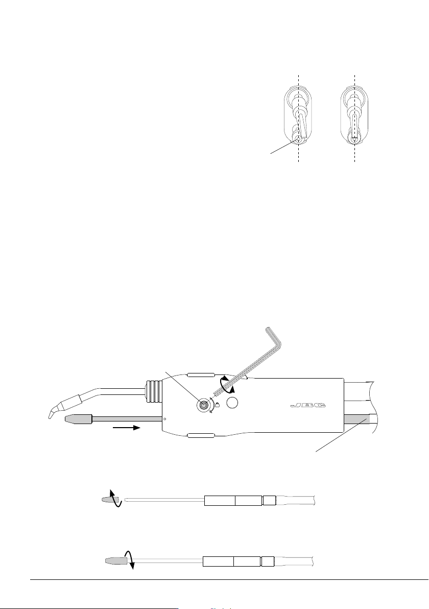
Cartridge Alignment Example
The cartridge should always be aligned with the exit of the outlet
nozzle. The image on the left shows a slightly deviated cartridge,
while the image on the right shows a properly aligned cartridge.
Use the alignment top tab before fixing the cartridge to make
sure the cartridge is well positioned.
Outlet Nozzle Replacement
Guide Tube
Set Screw
Guide Tube Set
Outlet Nozzle Exit
Not aligned
Aligned