manual-ale-automatic-feed-soldering-control-unit-jbc-0033469_ID-245046_EN.pdf - 第5页
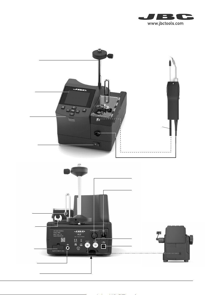
5 40 mm 50 mm 60 mm 80 mm 100 mm 130 mm 130 mm par a manuales - neg r o plano 200 mm 300 mm Power Socket and Main Fu se Ear th Fuse R J 12 Co nne ctor fo r FAE and Robot System USB-B Connect or USB-A Connect or Sol de r …
4
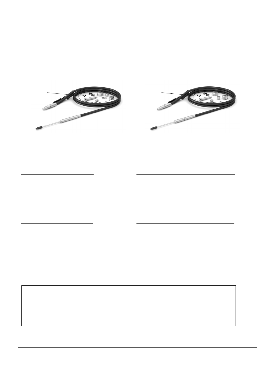
for wire ø 0.8 mm / ø 0.032 in
- Ref. GALE08V-B
for wire ø 1.0 mm / ø 0.040 in
- Ref. GALE10V-B
for wire ø 1.2 mm / ø 0.047 in
- Ref. GALE12V-B
for wire ø 1.6 mm / ø 0.063 in
- Ref. GALE16V-B
Components already
assembled in
Control Unit
for wire ø 0.38 - 0.4 mm / ø 0.015 - 0.016 in
- Ref. GALE04D-B
for wire ø 0.46 - 0.56 mm / ø 0.018 - 0.022 in
- Ref. GALE05D-B
for wire ø 0.80 - 0.82 mm / ø 0.032 - 0.033 in
- Ref. GALE08D-B
for wire ø 0.90 - 1.10 mm / ø 0.036 - 0.044 in
- Ref. GALE10D-B
Components already
assembled in
Control Unit
Without solder wire perforation:With solder wire perforation:
One of the following items is included according to purchased reference:
Solder Wire Guide Kit ............................................................................................................................. 1 unit
Note: For correct operation, the diameter of the solder wire in use must match the diameter
of the purchased guide kit.
Guide sets for different diameters are available at:
www.jbctools.com/solder-wire-guide-kit-product-2098.html
Packing List
5
40 mm
50 mm
60 mm
80 mm
100 mm
130 mm
130 mm
para manuales - negro plano
200 mm
300 mm
Power Socket
and Main Fuse
Earth Fuse
RJ12
Connector for FAE
and Robot System
USB-B
Connector
USB-A
Connector
Solder Wire
Inlet
Features and Connections
ALE250
Automatic-Feed
Soldering Iron*
ALE
Automatic-Feed
Soldering Control Unit
Main Switch
Display
Solder Reel
Stand
below
Equipotential
Connector
Pedal
Connector
ALES
Stand for ALE250
Automatic-Feed
Soldering Iron*
Allen Key
and Spanner
Storage
Peripherals
Connector
*not included
GALE
Solder Wire Guide
Kit for ALE250
availabe for
different solder
wire diameters
see page 11 + 12
325
º
C
24.0
mm/s
25% 75%
Power Con�nuous
50%
19:29
Sel. temp. 325
º
C
Ø 1.00 mm
Supplied: 12 mm
Language
Tool se�ngs
Counters
Reset
Exit
Feeder se�ngs
325
º
C
24.0
mm/s
25% 75%
Power Con�nuous
50%
Sel. temp. 325
º
C
Ø 1.00 mm
Supplied: 12 mm
Tin reload process
Mode Con�nuous
5.0mm/s
1.00mm
Off
None
Speed
Wire diameter
Feeder parameters lock
Backward
Back
325
º
C
24.0
mm/s
25%
75%
Power
Con�nuous
50%
Sel. temp. 325
º
C
Ø 1.00 mm
Supplied: 12 mm
Tin reload process
Forward
Backward
Place the �n on the gears
and press:
Press ok to exit
325
º
C
24.0
mm/s
25%
75%
Power
Con�nuous
50%
Sel. temp. 325
º
C
Ø 1.00 mm
Supplied: 12 mm
Program
Con�nuous
Discon�nuous
Mode
Back
0.5
mm/s
25%
75%
Power
Con�nuous
50%
19:29
Sel. Temp.
350
º
C
Ø 1.00 mm
Supplied: 0 mm
350
º
C
0.5
10.0
25%
75%
Power
Discon�nuous
50%
19:29
Sel. Temp.
350
º
C
Ø 1.00 mm
350
º
C
mm/s
mm
25%
75%
Power
50%
19:29
Sel. Temp.
350
º
C
350
º
C
3
2
1
Program #1
Ø 1.00 mm
325
º
C
24.0
mm/s
25%
75%
Power
Con�nuous
50%
Sel. temp. 325
º
C
Ø 1.00 mm
Supplied: 12 mm
Tin reload process
Mode
Con�nuous
20.0mm/s
1.00mm
Off
5.0mm
Speed
Wire diameter
Feeder parameters lock
Backward
Back
325
º
C
24.0
mm/s
25%
75%
Power
Con�nuous
50%
Sel. temp. 325
º
C
Ø 1.00 mm
Supplied: 12 mm
Feeder parameters lock
20.0mm/s
1.00mm
Off
5.0mm
Speed
Tin reload process
Wire diameter
Backward
Back
Mode
Con�nuous
325
º
C
24.0
mm/s
25% 75%
Power Con�nuous
50%
Sel. temp. 325
º
C
Ø 1.00 mm
Supplied: 12 mm
Feeder parameters lock
1.00mm
Off
2.0mm
Edit program
Programs loaded
Set default programs
Tin reload process
Wire diameter
Backward
Back
Mode Program
325
º
C
24.0
mm/s
25% 75%
Power Con�nuous
50%
Sel. temp. 325
º
C
Ø 1.00 mm
Supplied: 12 mm
Edit program
Program #1
Length Speed
3
2
1
mm
1.0 5.0
5.0 5.0
2.0 2.0
mm/s
325
º
C
24.0
mm/s
25%
75%
Power
Con�nuous
50%
Sel. temp. 325
º
C
Ø 1.00 mm
Supplied: 12 mm
Edit program
Length
Speed
3
2
1
mm
None
None
None
None
2.0
2.5
mm/s
Program #4
325
º
C
24.0
mm/s
25%
75%
Power
Con�nuous
50%
19:29
Sel. temp. 325
º
C
Ø 1.00 mm
Supplied: 12 mm
Language
Tool se�ngs
Counters
Reset
Exit
Feeder se�ngs
325
º
C
24.0
mm/s
25%
75%
Power
Con�nuous
50%
Sel. temp. 325
º
C
Ø 1.00 mm
Supplied: 12 mm
English
Deutsch
Español
Italiano
Français
日本語
한국어
Português
Pусский
325
º
C
24.0
mm/s
25%
75%
Power
Con�nuous
50%
Sel. temp. 325
º
C
Ø 1.00 mm
Supplied: 12 mm
Program version
8886732
Maximum temp
400
º
C
Off
200
º
C
On
º
C
mm
Minimum temp
Sound
PIN
Temp units
Length units
Sta�on reset
Back
325
º
C
24.0
mm/s
25%
75%
Power
Con�nuous
50%
Sel. temp. 325
º
C
Ø 1.00 mm
Supplied: 12 mm
Temp adjust
0
º
C
Temp level set
Off
10min
0min
150
º
C
Sleep delay
Peripher.
Sleep temp
Hiberna�on delay
Back
325
º
C
24.0
mm/s
25%
75%
Power
Con�nuous
50%
Sel. temp. 325
º
C
Ø 1.00 mm
Supplied: 12 mm
Plug hrs
28
Working hrs
Part
Tot
6
0
0
0
20
1
2
1
24
20
181
19
22786
118
Sleep hrs
Sleep cyc
Fed cyc
Fed mm
Hiber hrs
No tools hrs
325
º
C
24.0
mm/s
25%
75%
Power
Con�nuous
50%
Sel. temp. 325
º
C
Ø 1.00 mm
Supplied: 12 mm
Feeder parameters lock
20.0mm/s
1.00mm
12.0mm
Off
5.0mm
Speed
Tin reload process
Length
Wire diameter
Backward
Back
Mode
Discon�nuous
325
º
C
24.0
mm/s
25% 75%
Power Con�nuous
50%
Sel. temp. 325
º
C
Ø 1.00 mm
Supplied: 12 mm
Tin reload process
Mode Con�nuous
5.0mm/s
1.00mm
Off
None
Speed
Wire diameter
Feeder parameters lock
Backward
Back
325
º
C
24.0
mm/s
25% 75%
Power Con�nuous
50%
Sel. temp. 325
º
C
Ø 1.00 mm
Supplied: 12 mm
1.00mm
Upda�ng
Your sta�ons is being updated
No
Do you want to update firmware?
Yes
EARTH FUSE F1.25 A
USE ONLY WITH A 250 V FUSE
EARTH FUSE F1.25 A
325
º
C
24.0
mm/s
25%
75%
Power
Con�nuous
50%
19:29
Sel. temp. 325
º
C
Ø 1.00 mm
Supplied: 12 mm
Language
Tool se�ngs
Counters
Reset
Exit
Feeder se�ngs
325
º
C
24.0
mm/s
25%
75%
Power
Con�nuous
50%
Sel. temp. 325
º
C
Ø 1.00 mm
Supplied: 12 mm
Tin reload process
Mode
Con�nuous
5.0mm/s
1.00mm
Off
None
Speed
Wire diameter
Feeder parameters lock
Backward
Back
325
º
C
24.0
mm/s
25%
75%
Power
Con�nuous
50%
Sel. temp. 325
º
C
Ø 1.00 mm
Supplied: 12 mm
Tin reload process
Forward
Backward
Place the �n on the gears
and press:
Press ok to exit
325
º
C
24.0
mm/s
25%
75%
Power
Con�nuous
50%
Sel. temp. 325
º
C
Ø 1.00 mm
Supplied: 12 mm
Program
Con�nuous
Discon�nuous
Mode
Back
0.5
mm/s
25%
75%
Power
Con�nuous
50%
19:29
Sel. Temp.
350
º
C
Ø 1.00 mm
Supplied: 0 mm
350
º
C
0.5
10.0
25%
75%
Power
Discon�nuous
50%
19:29
Sel. Temp.
350
º
C
Ø 1.00 mm
350
º
C
mm/s
mm
25%
75%
Power
50%
19:29
Sel. Temp.
350
º
C
350
º
C
3
2
1
Program #1
Ø 1.00 mm
325
º
C
24.0
mm/s
25%
75%
Power
Con�nuous
50%
Sel. temp. 325
º
C
Ø 1.00 mm
Supplied: 12 mm
Tin reload process
Mode
Con�nuous
20.0mm/s
1.00mm
Off
5.0mm
Speed
Wire diameter
Feeder parameters lock
Backward
Back
325
º
C
24.0
mm/s
25%
75%
Power
Con�nuous
50%
Sel. temp. 325
º
C
Ø 1.00 mm
Supplied: 12 mm
Feeder parameters lock
20.0mm/s
1.00mm
Off
5.0mm
Speed
Tin reload process
Wire diameter
Backward
Back
Mode
Con�nuous
325
º
C
24.0
mm/s
25%
75%
Power
Con�nuous
50%
Sel. temp. 325
º
C
Ø 1.00 mm
Supplied: 12 mm
Feeder parameters lock
1.00mm
Off
2.0mm
Edit program
Programs loaded
Set default programs
Tin reload process
Wire diameter
Backward
Back
Mode
Program
325
º
C
24.0
mm/s
25%
75%
Power
Con�nuous
50%
Sel. temp. 325
º
C
Ø 1.00 mm
Supplied: 12 mm
Edit program
Program #1
Length
Speed
3
2
1
mm
1.0
5.0
5.0
5.0
2.0
2.0
mm/s
325
º
C
24.0
mm/s
25%
75%
Power
Con�nuous
50%
Sel. temp. 325
º
C
Ø 1.00 mm
Supplied: 12 mm
Edit program
Length
Speed
3
2
1
mm
None
None
None
None
2.0
2.5
mm/s
Program #4
325
º
C
24.0
mm/s
25%
75%
Power
Con�nuous
50%
19:29
Sel. temp. 325
º
C
Ø 1.00 mm
Supplied: 12 mm
Language
Tool se�ngs
Counters
Reset
Exit
Feeder se�ngs
325
º
C
24.0
mm/s
25%
75%
Power
Con�nuous
50%
Sel. temp. 325
º
C
Ø 1.00 mm
Supplied: 12 mm
English
Deutsch
Español
Italiano
Français
日本語
한국어
Português
Pусский
325
º
C
24.0
mm/s
25%
75%
Power
Con�nuous
50%
Sel. temp. 325
º
C
Ø 1.00 mm
Supplied: 12 mm
Program version
8886732
Maximum temp
400
º
C
Off
200
º
C
On
º
C
mm
Minimum temp
Sound
PIN
Temp units
Length units
Sta�on reset
Back
325
º
C
24.0
mm/s
25%
75%
Power
Con�nuous
50%
Sel. temp. 325
º
C
Ø 1.00 mm
Supplied: 12 mm
Temp adjust
0
º
C
Temp level set
Off
10min
0min
150
º
C
Sleep delay
Peripher.
Sleep temp
Hiberna�on delay
Back
325
º
C
24.0
mm/s
25%
75%
Power
Con�nuous
50%
Sel. temp. 325
º
C
Ø 1.00 mm
Supplied: 12 mm
Plug hrs
28
Working hrs
Part
Tot
6
0
0
0
20
1
2
1
24
20
181
19
22786
118
Sleep hrs
Sleep cyc
Fed cyc
Fed mm
Hiber hrs
No tools hrs
325
º
C
24.0
mm/s
25%
75%
Power
Con�nuous
50%
Sel. temp. 325
º
C
Ø 1.00 mm
Supplied: 12 mm
Feeder parameters lock
20.0mm/s
1.00mm
12.0mm
Off
5.0mm
Speed
Tin reload process
Length
Wire diameter
Backward
Back
Mode
Discon�nuous
325
º
C
24.0
mm/s
25%
75%
Power
Con�nuous
50%
Sel. temp. 325
º
C
Ø 1.00 mm
Supplied: 12 mm
Tin reload process
Mode
Con�nuous
5.0mm/s
1.00mm
Off
None
Speed
Wire diameter
Feeder parameters lock
Backward
Back
325
º
C
24.0
mm/s
25%
75%
Power
Con�nuous
50%
Sel. temp. 325
º
C
Ø 1.00 mm
Supplied: 12 mm
1.00mm
Upda�ng
Your sta�ons is being updated
No
Do you want to update firmware?
Yes
EARTH FUSE F1.25 A
USE ONLY WITH A 250 V FUSE
EARTH FUSE F1.25 A
Tool Assembly
Connect the tool to the control unit following these steps:
Loosen the set screw, insert and push the guide nozzle until it stops (1) and tighten the set screw (2)
again. Then plug in the tool connector (3).
1
3
Insert all the way in until it stops
Screw
2
ALE250
ALE250
ALE250
ALE250
ALE250
ALE250
ALE250
ALE250
ALE250
1
2
3
4
2
1
4
3
6
Mark
Cartridge Assembly
ALE250
Auto-Feed Soldering Iron
Cartridge Set Screw Guide Nozzle
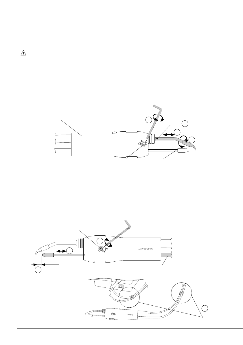
Open the guide tube set screw (1) and insert the guide tube set.
Adjust the guide tube length (2). Leave a gap of 5 to 7 mm (0.19 to 0.27 in) between the tip and the
outlet nozzle (3). Once the position is adjusted, tighten the guide tube set screw (1).
For a better handling, use the clips (4) to attach the guide tube to the tool cable.
Guide Tube Set Assembly
5-7 mm
0.19-0.27 in
Guide Tube
Set Screw
Guide Tube
Set
For a safe cartridge assembly, make sure that the tool is unplugged and that any cartridge in place
has cooled down before following these guidelines:
Loosen the cartridge set screw (1) and insert the cartridge up to its mark (2).
Important: It is essential to insert the cartridge completely for a good connection. Use the mark as
reference (3).
Adjust the cartridge tip direction (4) and tighten the cartridge set screw (1).
Clips