Gemini Semi Appendix Manual.pdf - 第21页
INSTALLATION APPENDIX SAFETY FEATURES Chapter Issue 1 Feb 15 Appendix to Micron Technical Manuals 2.3 Paste Roll Height Monitor Option - Label If the machine is fitted with an optional Paste Roll Height monitor , then a …
INSTALLATION APPENDIX
SAFETY FEATURES
2.2 Appendix to Micron Technical Manuals Chapter Issue 1 Feb 15
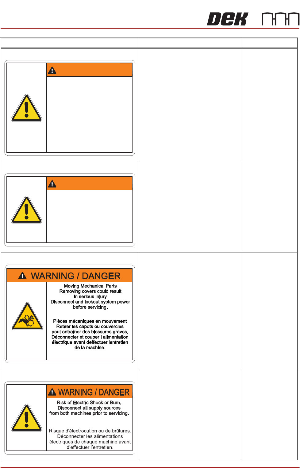
ELECTRO MECHANICAL HAZARDS
Removing this cover exposes electro-
mechanical parts that have the potential
to cause serious injury. Disconnect and
lock out the system power before remov-
ing this cover. Refer to the Lockout
procedure at the end of this chapter.
GENERAL WARNING
Refer to the Operator manual or the front
of the Technical Reference manual
Safety chapter for a list of all warnings
and their definitions.
Lower Front Panel
Lower Rear Panel
POTENTIAL HAZARDS Potential dam-
age to the machines may occur if the
machines are separated without the
electrical link being disconnected.
Ensure both machines are powered
down and locked out prior to disconnect-
ing this electrical link.
GENERAL WARNING
Refer to the Operator manual or the front
of the Technical Reference manual
Safety chapter for a list of all warnings
and their definitions.
Rear Left Hand and
Right Hand Corner
Panels
MOVING MECHANICAL PARTS
Removing this cover exposes moving
mechanical parts that have the potential
to cause serious injury. Disconnect and
lock out the system power before remov-
ing this cover. Refer to the Lockout
procedure at the end of this chapter.
GENERAL WARNING
Refer to the Operator manual or the front
of the Technical Reference manual
Safety chapter for a list of all warnings
and their definitions.
Left and Right Rear
Corner Panels
ELECTRIC SHOCK OR BURNS
Disconnect all supply sources from both
machines prior to beginning servicing to
avoid electric shock or burns.
GENERAL WARNING
Refer to the Operator manual or the front
of the Technical Reference manual
Safety chapter for a list of all warnings
and their definitions.
Above Mains Isolator
Switch
Warning Definition Location
WARNING / DANGER
Electro Mechanical Hazards
Removing cover could result
in serious injury
Disconnect and lock out system
power before servicing refer to
the Technical Reference manual
Electro Mechanical Hazards
Removing cover could result
in serious injury
Disconnect and lock out system
power before servicing refer to
the Technical Reference manual
Dangers électromécaniques
Retirer les capots ou couvercles peut
entraîner des blessures graves.
Déconnecter et couper l alimentation
électrique avant deffectuer lentretien
de la machine, se référer
au Manuel de Référence Technique.
Dangers électromécaniques
Retirer les capots ou couvercles peut
entraîner des blessures graves.
Déconnecter et couper l alimentation
électrique avant deffectuer lentretien
de la machine, se référer
au Manuel de Référence Technique.
WARNING / DANGER
Potential Hazards Removing Cover,
ensure link between machines is
disconnected prior to moving
machinery
Potential Hazards Removing Cover,
ensure link between machines is
disconnected prior to moving
machinery
Retirer les capots ou couvercles peut
entraîner des blessures graves.
Déconnecter le lien entre les deux
machines avant tour déplacement.
Retirer les capots ou couvercles peut
entraîner des blessures graves.
Déconnecter le lien entre les deux
machines avant tour déplacement.
INSTALLATION APPENDIX
SAFETY FEATURES
Chapter Issue 1 Feb 15 Appendix to Micron Technical Manuals 2.3
Paste Roll Height
Monitor Option -
Label
If the machine is fitted with an optional Paste Roll Height monitor, then a Class
2 laser product label is attached to the outside of the machine next to the
nameplate.
EMO The machine is fitted with two Emergency Machine Off push button control
switches (EMO’s) located at the front and rear of the machines. Operation of
an EMO shuts down both machines.
Cover The printhead cover is fitted with a cam interlock switch to protect personnel
from internal moving parts.
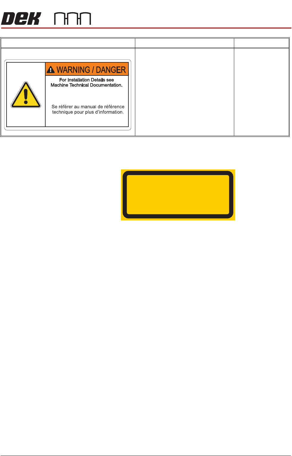
INSTALLATION DETAILS
For installing details for solvent tank see
the machine techncial documentation.
GENERAL WARNING
Refer to the Operator manual or the front
of the Technical Reference manual
Safety chapter for a list of all warnings
and their definitions.
Solvent Tank
Warning Definition Location
LASER RADIATION
DO NOT STARE INTO BEAM
CLASS 2 LASER PRODUCT
INSTALLATION APPENDIX
SAFETY FEATURES
2.4 Appendix to Micron Technical Manuals Chapter Issue 1 Feb 15
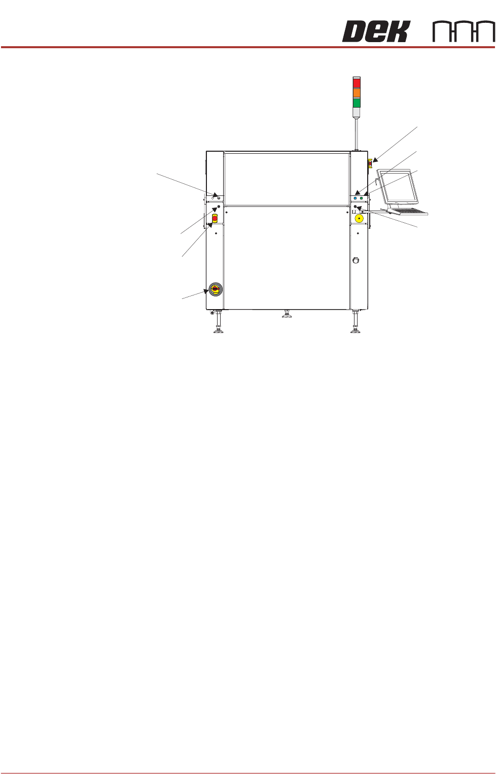
Figure 2-1 Machine Controls
Lid Bolt A pneumatically operated lid bolt is fitted to prevent the printhead cover from
being raised during the print cycle.
The lid bolt is withdrawn and the printhead cover may be raised:
• When Open Cover is requested by software
• When pause or stop is selected during a print cycle
• When the EMO is pressed
Safety Devices The safety features designed into this machine are for the protection of all
operator and maintenance personnel. ASM strongly recommend safety
devices are never overridden.
Two Button
Control Switches
The two button control switches or jog switches are positioned such as to
maintain maximum safety for the operator whilst solvent priming or paper
feeding with the printhead cover open. This requires both buttons to be
depressed simultaneously for the function to become active. The use of these
buttons is dependent on the function selected on the machine monitor. During
normal operation these buttons control paper feed and solvent prime opera-
tions. When in maintenance mode, the two button control switches control the
following diagnostics:
• Print Carriage
• Squeegee Assembly
• Camera Axes
• Rail System
EMO
View on Front of Machine 1
System Button
Start Button
Right Jog Button
Internal
Light
Left
Jog Button
Mains
Isolator
Switch
EMO