Gemini Semi Appendix Manual.pdf - 第88页
TECHNICAL REFERENCE APPENDIX CALIBRATIONS 3.50 Appendix to Micron Technical Manuals Chapter Issue 1 Feb 15 The following window is displayed: 17. Select Confirm to save the n ew print height. 18. Select Cancel to close t…
TECHNICAL REFERENCE APPENDIX
CALIBRATIONS
Chapter Issue 1 Feb 15 Appendix to Micron Technical Manuals 3.49
Rising Table Style 1
Print Height Print reference height is the height to which the rising table is taken to achieve
board clamp to screen contact at zero board thickness. Print height is the height
the rising table is taken to print the product and is calculated as the print
reference height minus the board thickness and print gap. This calibration
accurately sets the board to screen ‘set contact height’ and ensures constant
print pressure is applied. Deterioration in this calibration may result in inconsist-
ent print pressure thereby effecting the print quality.
1. Ensure that a screen is fitted in the machine.
2. Select Maintenance.
3. Select Diagnostics.
4. Use Next or Previous to highlight Rising Table.
5. Select Select Module.
6. Ensure that Home Rising Table is highlighted.
7. Select Run Diagnost.
8. Use Next or Previous to highlight Set Reference Print Height.
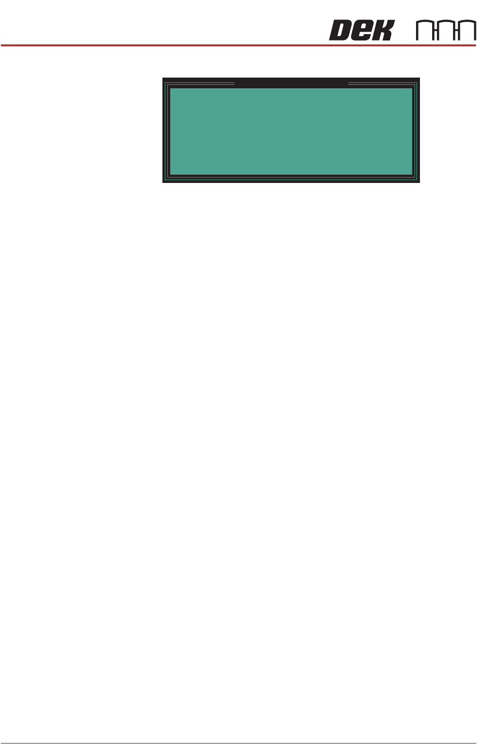
9. Select Run Diagnost. The following window is displayed:
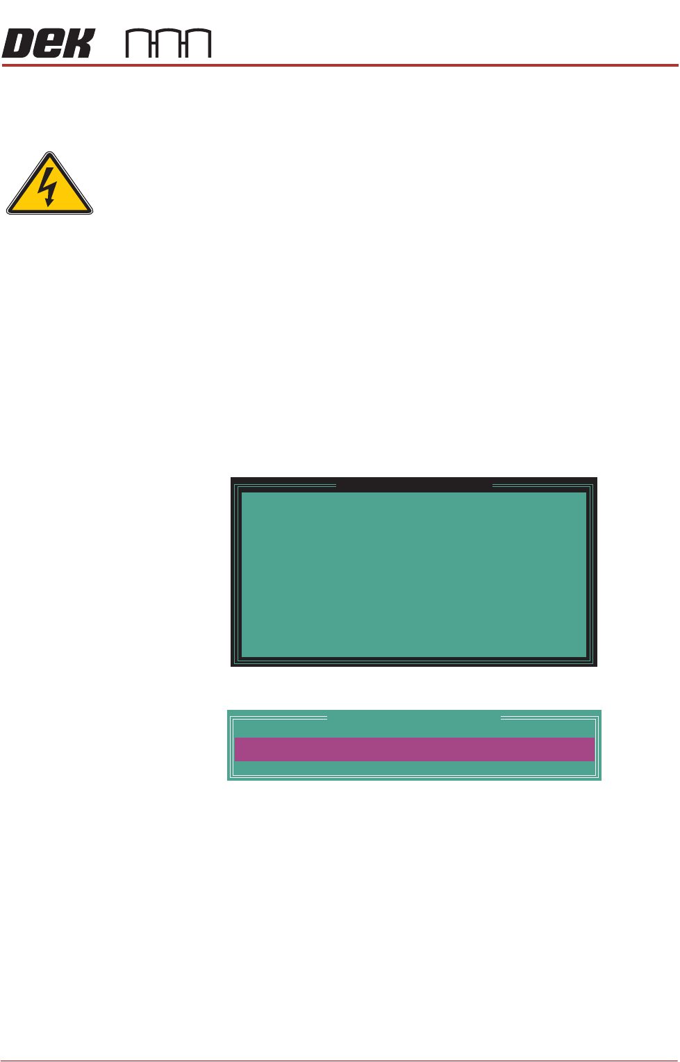
10.Select Confirm. The following window is displayed:
11. Open the front printhead cover.
12.Check the gap between the top of the transport rails and the screen. The
correct print height is when the top of the transport rails is just touching the
screen.
13.Use the Incr. or Decr. button to adjust the displayed dimension.
14.Select Move.
15.Repeat Steps 11 to 13 until the top of the transport rails are in contact with
the screen, without force.
16.When the correct height has been achieved, select Set Height.
SEMI 2
Please confirm the following:
There is a screen loaded.
There is NO board loaded.
The aim of this calibrationisto set the elevation of
the rising tableto the point where the closed board
clamps are just in contact with the stencil.
Whilefoil-less clamps orsnuggers are beingused,
ensure they have been adjusted to bring their top
surface levelwith
the top surface of the board.
Upon completion of this calibration, the Squeegee
Reference Height shouldalso be calibrated.
Set Reference Print Height
PRINT HEIGHT
Table Print Height Calibration
127.00
mm
TECHNICAL REFERENCE APPENDIX
CALIBRATIONS
3.50 Appendix to Micron Technical Manuals Chapter Issue 1 Feb 15
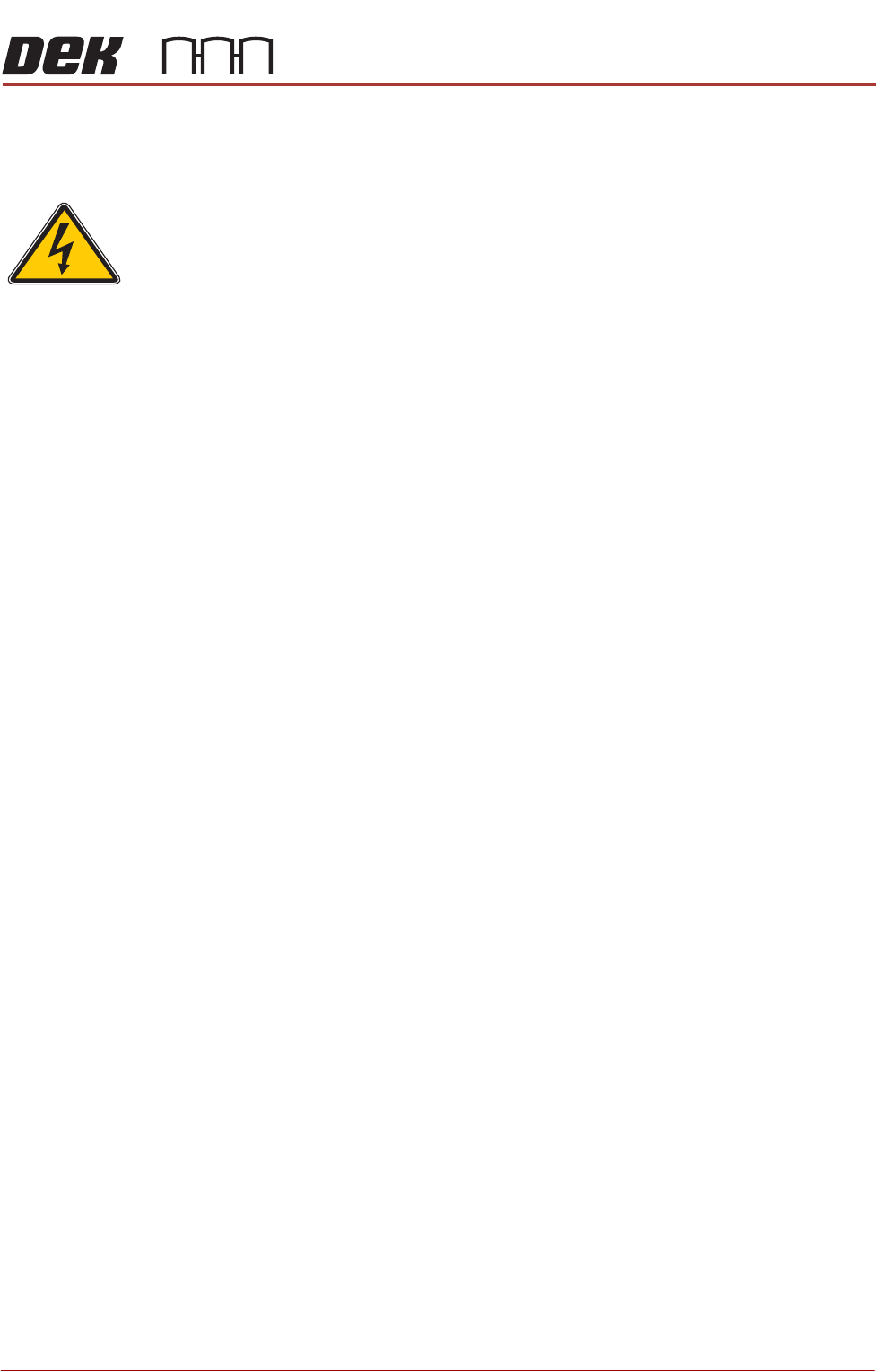
The following window is displayed:
17.Select Confirm to save the new print height.
18.Select Cancel to close the Set Reference Vision Height window.
19.Close the front printhead cover.
20.Press the System button.
21.Select Exit.
22.Select Exit.
23.Select Back.
24.Carry out the Squeegee Reference Height calibration, Squeegee chapter
refers.
Please confirm the following:
The board clamps are not lifting the stencil.
When the part of the stencil that is over the board
clampsispressed, there is noperceptiblemovement.
To adjust the elevation of the board clamps, press
Cancel. Use Incr. And Decr. to alter the value of print
height. Use Move
to apply the current value of print
height.
Set Reference Vision Height
TECHNICAL REFERENCE APPENDIX
CALIBRATIONS
Chapter Issue 1 Feb 15 Appendix to Micron Technical Manuals 3.51
MMI
Touchscreen
Calibration
To recalibrate the touchscreen carry out the following procedure:
1. To access the Start button on the Windows task bar, press the Windows
key.
2. Select Programs, Touchscreen and 4pts Cal.
3. Follow the on screen instructions.
4. Touchscreen calibration is now complete.
5. Restore the DEK program.
SEMI 2