Gemini Semi Appendix Manual.pdf - 第22页
INSTALLATION APPENDIX SAFETY FEATURES 2.4 Appendix to Micron Technical Manuals Chapter Issue 1 Feb 15 Figure 2-1 Machine Contro ls Lid Bolt A pneumatically operated lid bo lt is fitted to prevent the printhead cover from…
INSTALLATION APPENDIX
SAFETY FEATURES
Chapter Issue 1 Feb 15 Appendix to Micron Technical Manuals 2.3
Paste Roll Height
Monitor Option -
Label
If the machine is fitted with an optional Paste Roll Height monitor, then a Class
2 laser product label is attached to the outside of the machine next to the
nameplate.
EMO The machine is fitted with two Emergency Machine Off push button control
switches (EMO’s) located at the front and rear of the machines. Operation of
an EMO shuts down both machines.
Cover The printhead cover is fitted with a cam interlock switch to protect personnel
from internal moving parts.
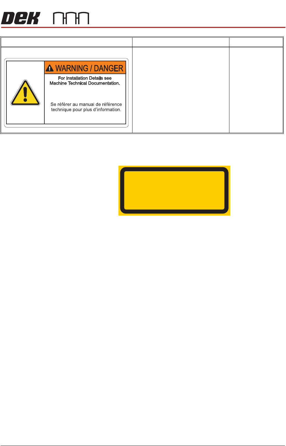
INSTALLATION DETAILS
For installing details for solvent tank see
the machine techncial documentation.
GENERAL WARNING
Refer to the Operator manual or the front
of the Technical Reference manual
Safety chapter for a list of all warnings
and their definitions.
Solvent Tank
Warning Definition Location
LASER RADIATION
DO NOT STARE INTO BEAM
CLASS 2 LASER PRODUCT
INSTALLATION APPENDIX
SAFETY FEATURES
2.4 Appendix to Micron Technical Manuals Chapter Issue 1 Feb 15
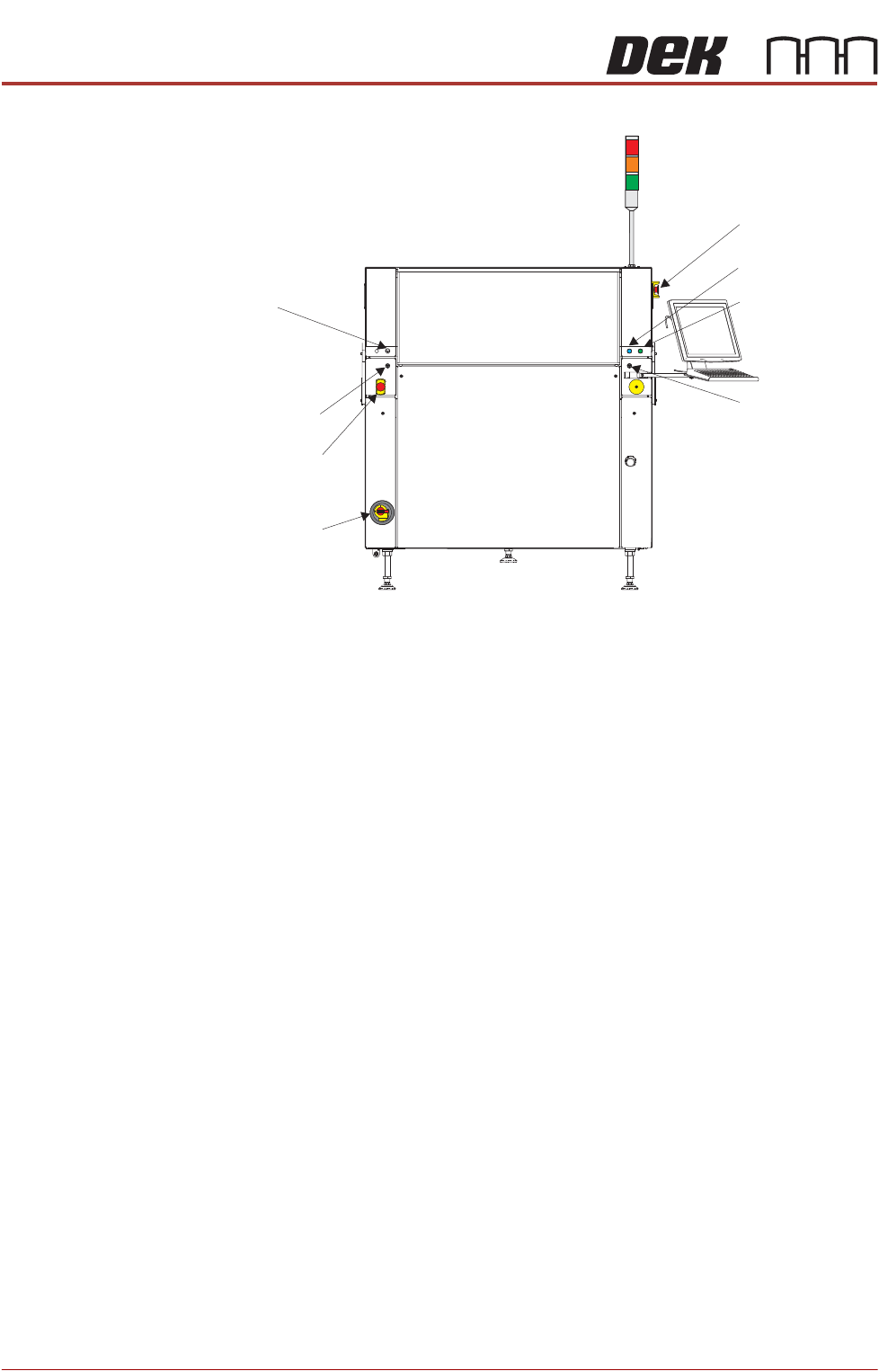
Figure 2-1 Machine Controls
Lid Bolt A pneumatically operated lid bolt is fitted to prevent the printhead cover from
being raised during the print cycle.
The lid bolt is withdrawn and the printhead cover may be raised:
• When Open Cover is requested by software
• When pause or stop is selected during a print cycle
• When the EMO is pressed
Safety Devices The safety features designed into this machine are for the protection of all
operator and maintenance personnel. ASM strongly recommend safety
devices are never overridden.
Two Button
Control Switches
The two button control switches or jog switches are positioned such as to
maintain maximum safety for the operator whilst solvent priming or paper
feeding with the printhead cover open. This requires both buttons to be
depressed simultaneously for the function to become active. The use of these
buttons is dependent on the function selected on the machine monitor. During
normal operation these buttons control paper feed and solvent prime opera-
tions. When in maintenance mode, the two button control switches control the
following diagnostics:
• Print Carriage
• Squeegee Assembly
• Camera Axes
• Rail System
EMO
View on Front of Machine 1
System Button
Start Button
Right Jog Button
Internal
Light
Left
Jog Button
Mains
Isolator
Switch
EMO
INSTALLATION APPENDIX
SAFETY FEATURES
Chapter Issue 1 Feb 15 Appendix to Micron Technical Manuals 2.5
• Screen Alignment
• Rising Table
Only one button is required to drive the selected mechanism, the two buttons
are used to drive the mechanism in opposite directions, ie jog forward or jog
back.
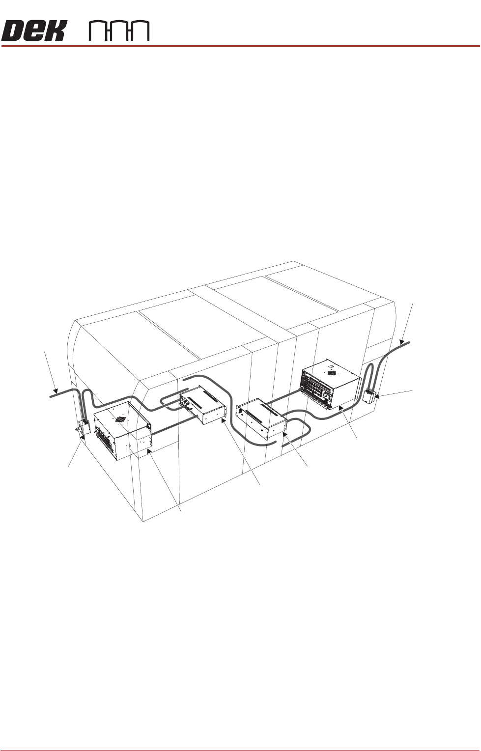
Emergency
Shutdown
If an emergency stop is initiated via an EMO, all power and pneumatics to the
paired machines are removed. Electrical power remains to the M39 EMO
enclosure via the mains isolator but is removed from there to the M37 power
supply unit. Switching mains isolator to OFF removes electrical power from the
M39 EMO enclosure. Pneumatic supply is also closed off and any pressurised
air remaining within the machine’s system is vented via the pneumatic dump
valve.
Figure 2-2 Mains Electrical Supply
From Factory
Mains Supply
Mains Isolator
Switch
M39 EMO Enclosure
M37 Power
Supply Enclosure
M37 Power
Supply Enclosure
Mains Isolator
Switch
From Factory
Mains Supply
M39 EMO Enclosure