00198327-01_MM_Vacuumpump_Becker_VX25_DE_EN.pdf - 第47页
2 Maintenance Tasks for Vacuum Pump 2.4 Performing Maintenance Tasks Maintenance Manual / Instandhaltungsanleitung Vacuum Pump / Vakuumpumpe Becker VX25 06/2017 47 Fig.15: Sliders ► Carefully lever the slides (1) out of…
2 Maintenance Tasks for Vacuum Pump
2.4 Performing Maintenance Tasks
46 Maintenance Manual / Instandhaltungsanleitung Vacuum Pump / Vakuumpumpe Becker VX25 06/2017
2.4.2 Checking/Replacing the Slide Set
Depending on the installation situation, removing the vacuum pump for maintenance tasks can be
useful. Refer to the appropriate vacuum pump assembly instructions for your machine for this.
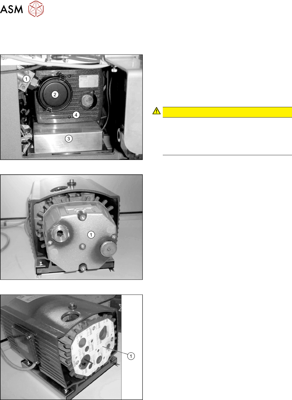
Fig.12: Preparing the vacuum pump
► Loosen the quick-release connector inside the fil-
ter casing (2) and the distribution block(1).
► Dismantle the filter casing(2).
► Dismantle the air outlet conduit(3) (see the
assembly instructions).
► Dismantle the front cover(4).
CAUTION!
The front plate of the vacuum pump is only fixed
with rubber buffers.
Take care not to damage the rubber buffers.
Always lift the vacuum pump on its housing or fil-
ter, not on the front plate.
.
Fig.13: Cover
► Dismantle the cover(1).
Fig.14: Housing
► Dismantle the housing(1).
► Use a vacuum to clean the housing.
2 Maintenance Tasks for Vacuum Pump
2.4 Performing Maintenance Tasks
Maintenance Manual / Instandhaltungsanleitung Vacuum Pump / Vakuumpumpe Becker VX25 06/2017 47
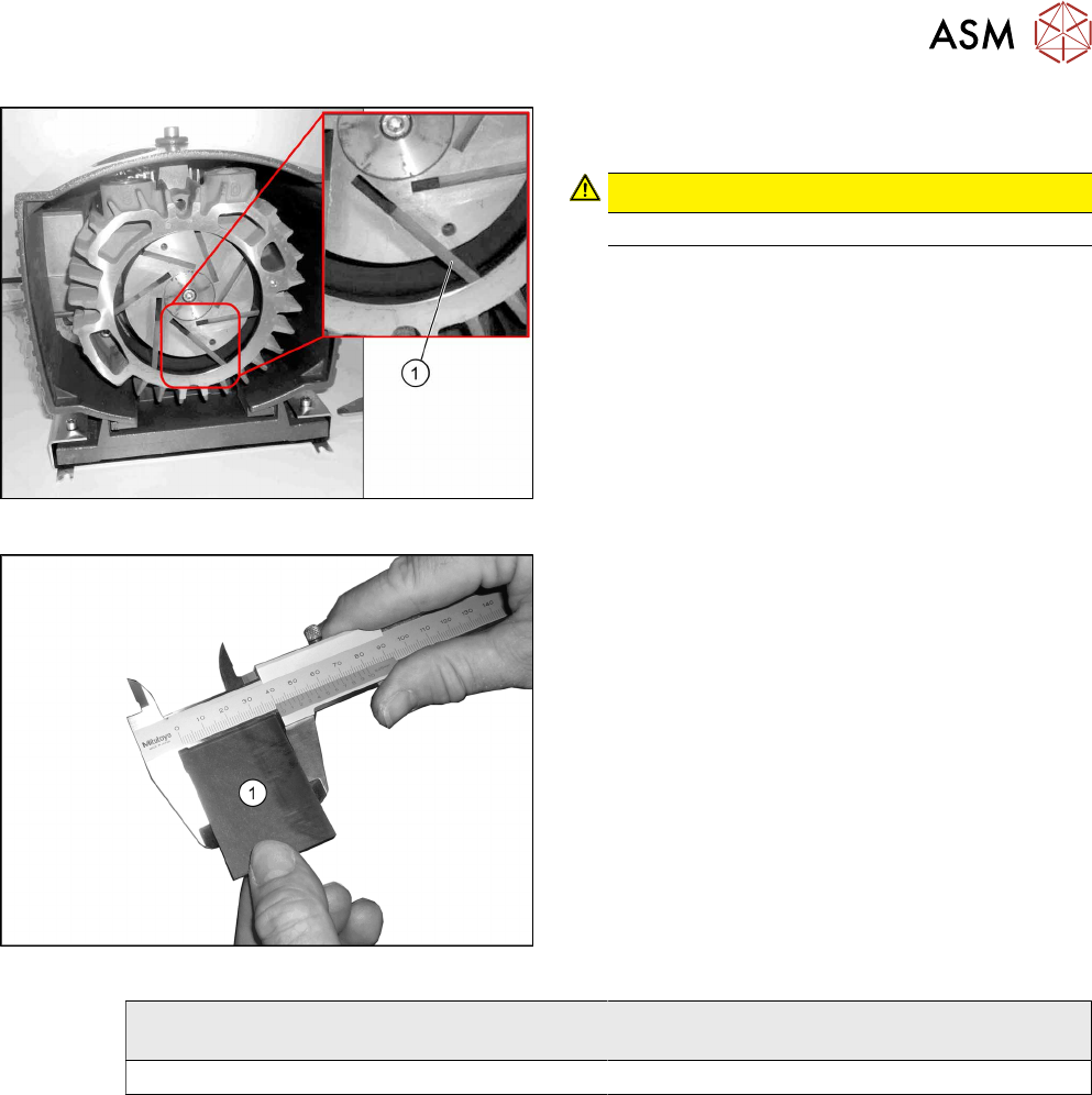
Fig.15: Sliders
► Carefully lever the slides (1) out of the pump. (7
pieces)
CAUTION!
The slides are sensitive.
.
► Check the condition of the slides and replace the
slides, if required.
Fig.16: Measuring the width of the slides
► Measure the width of the slides. Replace a slide if
it doesn't reach the required minimum width (see
the following table).
Pump type
(see type label at the front cover)
Minimum allowed width of the slide
DX / VX / T 4.25 Min. 28 mm
2 Maintenance Tasks for Vacuum Pump
2.5 Final work
48 Maintenance Manual / Instandhaltungsanleitung Vacuum Pump / Vakuumpumpe Becker VX25 06/2017
2.5 Final work
► Installation is performed by following the above instructions in the reverse order. Also observe
the following instructions:
Fig.17: Protections on the manual tables
Manual tables only:
WARNING!
There is a risk of injury on manual tables without
the two protections.
.
► Fit the two protections.
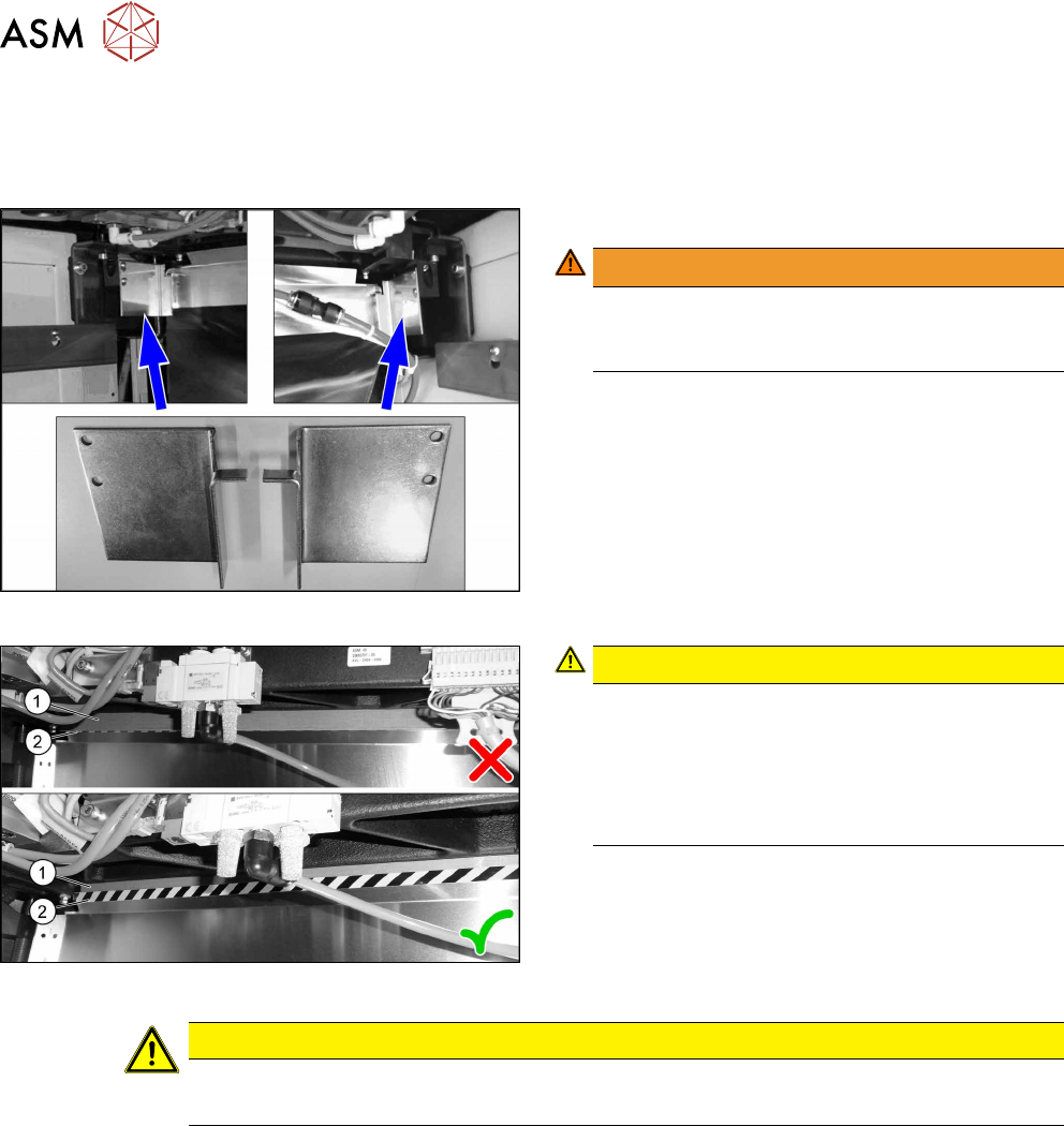
Fig.18: Plastic strips on SIPLACE SX1/SX2
CAUTION!
Make sure that the plastic strips (1) (if present)
are located behind the plate (2) when you hook
up the used tape chute.
The black-yellow hatched label must be com-
pletely visible.
.
CAUTION
Waste slide
► Install the waste slide.