ISM6636A&B_Rev1.10解密.pdf - 第30页
30 Innovision Semiconductor Preliminary Datas heet ISM6636 A/B Rev1.10 01/2023 Register = 0x17 Overvoltage protection threshold setting (OV_Thresho ld) The overvoltage p rotection function is realized b y monitoring th e…
29
Innovision Semiconductor
Preliminary Datasheet
ISM6636A/B
Rev1.10 01/2023
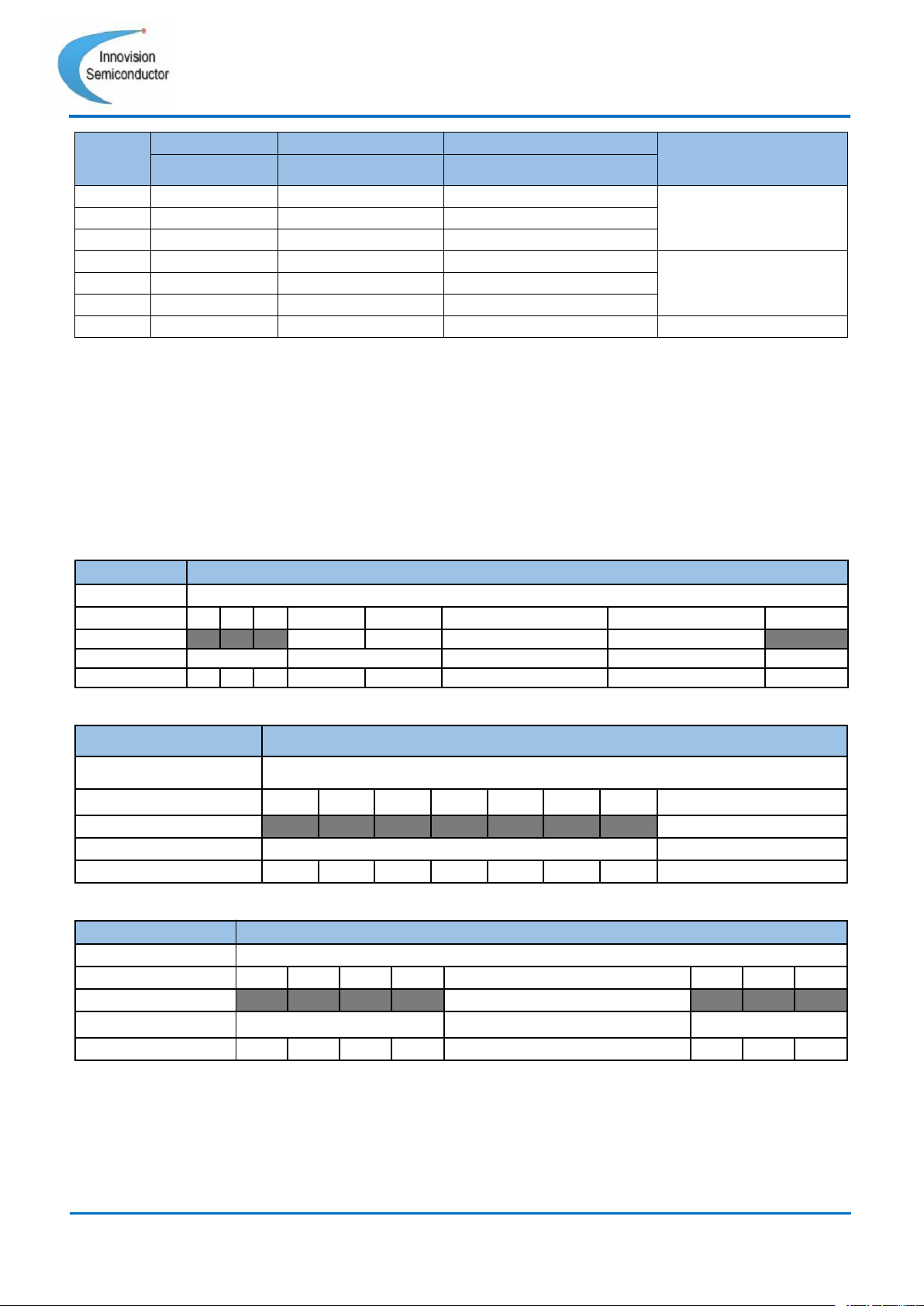
EN pin
I2C ENABLE
Soft Stop Enable
Soft Stop Power down
State
0x1B[0]
0x14[2]
0x1C[3]
0
0
\
\
Power Off
1
0
\
\
0
1
\
\
1
1
0
0
Power On
1
1
0
1
1
1
1
0
1
1
1
1
Soft Stop Power down
Table 19 Start and power off (“\” means ignore the state of this register)
ISM6636X supports forced continuous mode and discontinuous conduction mode (FCCM
and DCM), which can be set through register 0x14 Bit [1]. The rules are as follows:
•
When 0x14 Bit[1] = 0, the module will be in forced continuous mode (FCCM).
• When 0x14 Bit[1] = 1 and EN pin input voltage is lower than 2.5V, the module will be in
discontinuous conduction mode (DCM).
• When 0x14 Bit[1] = 1 and EN pin input voltage is higher than 2.5V, the module will be
in forced continuous mode (FCCM).
Command
Soft Start and Switch Mode
Format
unsigned binary
Bit
7
6
5
4
3
2
1
0
Access
R
R
R
R/W
R/W
R/W
R/W
R
Function
no use
Soft Start_Rate
Soft Stop Enable
FCCM and DCM
no use
Default
0
0
0
0
0
0
1
0
Table 20 Register = 0x14
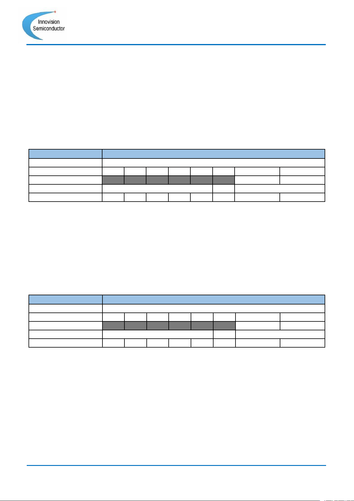
Command
I2C Enable
Format
unsigned binary
Bit
7
6
5
4
3
2
1
0
Access
R
R
R
R
R
R
R
R/W
Function
no use
I2C Enable
Default
0
0
0
0
0
0
0
0
Table 21 Register = 0x1B
Command
Soft Stop Power down
Format
unsigned binary
Bit
7
6
5
4
3
2
1
0
Access
R
R
R
R
R/W
R
R
R
Function
no use
Soft Stop Power down
no use
Default
0
0
0
0
0
0
0
0
Table 22 Register = 0x1C
30
Innovision Semiconductor
Preliminary Datasheet
ISM6636A/B
Rev1.10 01/2023
Register = 0x17 Overvoltage protection threshold setting
(OV_Threshold)
The overvoltage protection function is realized by monitoring the voltage of the VOS pin.
The module will compare the voltage collected by VOS with the set voltage. When the VOS
voltage exceeds the output overvoltage protection threshold (OV) for 5us, over voltage
protection will kick in, and the high side FET will no longer be turned on. And when it is
detected that the current of the low side FET dips below 0A, it enters a tri-state. The
overvoltage protection thresholds are set as follows:
[1:0]=00 : 105%; [1:0]=01 : 110%; [1:0]=10 : 115%; [1:0]=11 : 120%;
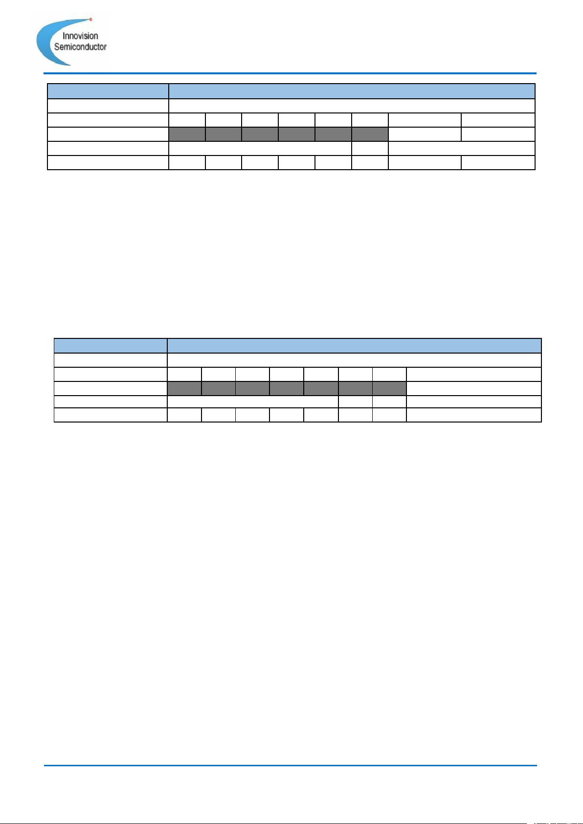
Command
OV_Threshold
Format
unsigned binary
Bit
7
6
5
4
3
2
1
0
Access
R
R
R
R
R
R
R/W
R/W
Function
no use
OV_Threshold
Default
0
0
0
0
0
0
1
1
Table 23 Register = 0x17
Register = 0x18 Power Indication Threshold (PG_Threshold)
The power indicator function will be turned on after the soft start (Soft Start), and the PG will
be in a de-asserted state before the soft start (Soft Start). This function is judged by the
VOS monitoring voltage. When the voltage collected by VOS is above the power indication
threshold, the PG signal will be pulled high. When the voltage collected by VOS is 5% lower
than the power indication threshold, the PG signal will be pulled low.
[1:0]=00 : 80%; [1:0]=01 : 85%; [1:0]=10 : 90%; [1:0]=11 : 95%;
Command
PG_Threshold
Format
unsigned binary
Bit
7
6
5
4
3
2
1
0
Access
R
R
R
R
R
R
R/W
R/W
Function
no use
PG_Threshold
Default
0
0
0
0
0
0
1
0
Table 24 Register = 0x18
Register = 0x19 Over-temperature protection threshold setting
(OT_Threshold)
The ISM6636X provides an adjustable over-temperature protection threshold setting
function. When the module temperature exceeds the temperature setting threshold, the
module will stop turning on the high side FET and reset the internal soft-start time. At this
point the internal LDO is still running. When the detected temperature drops to a working
range, the module will automatically restart. The hysteresis of over temperature protection
is about 20°C or so. The threshold settings for over temperature protection are as follows.
[1:0]=00 : 75°C; [1:0]=01 : 85°C; [1:0]=10 : 125°C; [1:0]=11 : 145°C;
31
Innovision Semiconductor
Preliminary Datasheet
ISM6636A/B
Rev1.10 01/2023
Command
OT_Threshold
Format
unsigned binary
Bit
7
6
5
4
3
2
1
0
Access
R
R
R
R
R
R
R/W
R/W
Function
no use
OT_Threshold
Default
0
0
0
0
0
0
1
0
Table 25 Register = 0x19
Register = 0x1A Overvoltage protection behavior setting
(OV_Response)
This register can set the behavior of the module after overvoltage protection occurs and can
choose to latch off or not. When the user chooses to latch off (Register 0x1A Bit[0]=0), the
module will be latched off after the overvoltage protection behavior occurs, until the user
resets EN or re-enables the I2C Enable. When the user chooses not to latch (register 0x1A
Bit[0]=1), the module will attempt to restart after the overvoltage protection occurs.
Table 26 Register = 0x1A
Register = 0x21 Status monitoring (Status)
ISM6636X can read the current state of the device through the register. The specific
function description is as follows:
•
Bit[3]=1: When this bit is high, it means the module is in the enabled state. (EN pin = 1
and I2C Enable = 1).
•
Bit[4]=1: When this bit is high, it means that the module is in over temperature state.
This bit is 0 when the module is not in an overtemperature state.
• Bit[5]=1: When this bit is high, it means the module is in overcurrent state. When the
module is not in an overcurrent state, this bit is 0.
• Bit[6]=1: When this bit is high, it means the module is in overvoltage state. When the
module is not in an overvoltage state, this bit is 0.
• Bit[7]=1: When this bit is high, it means that the module is in normal working state, the
state logic is consistent with PG, but there is only one I2C interface.
When the protection occurs, the above status bits can help the user to check which
protection mechanism the module is in.
Command
OV_Response
Format
unsigned binary
Bit
7
6
5
4
3
2
1
0
Access
R
R
R
R
R
R
R
R/W
Function
no use
OV_Response
Default
0
0
0
0
0
0
0
0