Infinity EX Rail System Module.pdf - 第24页
INFINITY EX RAIL S YSTEM M ODULE CALIBR ATIONS 15.2 4 Technical Reference Manual Chapter Issue 2 Jan 04 CALIBRA TION S Board T ransport Belt Speed The front and rear board transport belts (feed er belts) are driv en inde…
INFINITY
EX
RAIL SYSTEM MODULE
ADJUSTMENTS AND SETTINGS
Chapter Issue 2 Jan 04 Technical Reference Manual 15.23
NOTE
If any of the rail widths are out of tolerance do not adjust the rails, adjust the
position of the rail home position sensor and recheck.
9. Using a suitable test board, with the rail width programmed to the board size,
select Cycle Board on Belts.
10.Select Run and ensure the board runs through the entire length of the rail
system for 10 complete cycles, without jamming or excessive clicking of the
board edges.
NOTE
If any jamming occurs investigate the position of the board/snugger clamps, mid
rails and the green inserts at the rail ends before repeating the check.
Rail Shock
Absorber Setting
1. Ensure the machine is powered down.
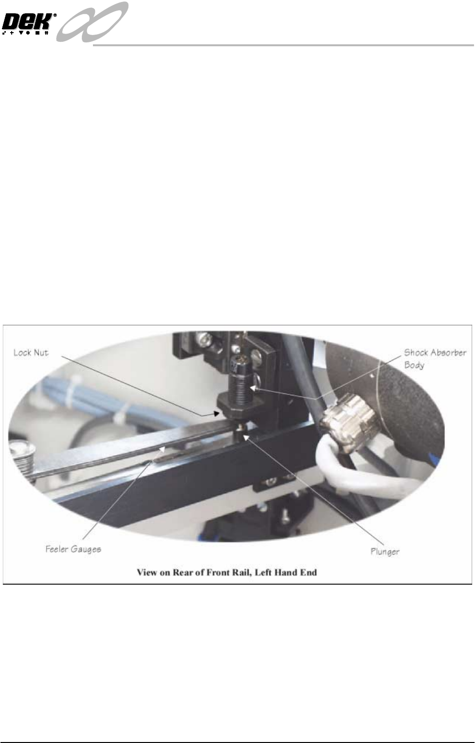
2. Using feeler gauges, check that a gap of 2.5mm - 3mm exists between the
top of the plunger and the shock absorber body. Alternatively use a 2.5mm
and 3mm allen key as a Go, No Go Gauge.
3. Repeat Step 2 for the three other rail shock absorbers.
4. If adjustment is necessary, slacken the lock nut.
5. Rotate the shock absorber body as required, clockwise to reduce the gap,
anti-clockwise to increase the gap.
6. Check the gap is between 2.5mm - 3mm.
7. Repeat Steps 5 and 6 until the correct dimension is achieved
8. Tighten the lock nut.
9. Recheck the gap is still within limits.
INFINITY
EX
RAIL SYSTEM MODULE
CALIBRATIONS
15.24 Technical Reference Manual Chapter Issue 2 Jan 04
CALIBRATIONS
Board Transport
Belt Speed
The front and rear board transport belts (feeder belts) are driven independently
by two variable speed motors. Inevitably one motor drives faster than the other
motor. It is necessary to calibrate these motors so that they drive at the same
speed in either direction. Non-compliance of this calibration could cause boards
to jam in the machine or uneven wear in the rails or transport belts.
WARNING
LETHAL VOLTAGE. DANGEROUS VOLTAGES EXIST IN THIS
EQUIPMENT. ENSURE ALL ELECTRONIC COVERS AND MAIN
MACHINE COVERS ARE FITTED BEFORE OPERATING THIS
EQUIPMENT.
The speed of both feeder belt motors is controlled by a MultiMove card situated
in the machine control enclosure and utilizes Pulse Width Modulation (PWM).
This is achieved by controlling the period of the 'ON' control pulse provided by
the MultiMove control card. The pulse repetition rate is fixed at 125Hz.
Feeder motor speed is measured using a tachometer on the input or output pulley
and adjusted by using the Belt Speed Calibration Page in the machine diagnos-
tics.
NOTE
For belt speed calibration set up see Calibration Procedure of this section. For
detailed information on access and use of the diagnostics module refer to the
Diagnostics chapter of the User manual.
Motor speed software parameters is listed in the following table:
Calibration
Procedure
1. In Diagnostics, select Rail System.
2. Select Belt Speed Calibration, the following window is displayed:
Name Maximum Minimum Default Increment
Front L to R Speed 64000 0 32000 1
Rear L to R Speed 64000 0 32000 1
Front R to L Speed 64000 0 32000 1
Rear R to L Speed 64000 0 32000 1
SEMI 2
Belt Speed Calibration
FRONT L TO R SPEED
FRONT R TO L SPEED
REAR L TO R SPEED
REAR R TO L SPEED
50000
50000
63999
63999
INFINITY
EX
RAIL SYSTEM MODULE
CALIBRATIONS
Chapter Issue 2 Jan 04 Technical Reference Manual 15.25
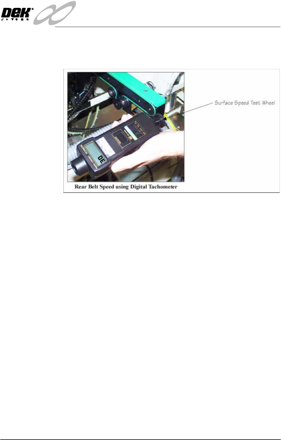
3. Using a tachometer fitted with the surface speed test wheel, positioned on the
input or output pulley of the front belt motor, measure the speed of the motor
left to right. Adjust the motor speed using Incr./Decr. to achieve a speed of
29 - 31 metres/min.
4. Using Next repeat Step 3 for front right to left motor speed.
5. Select Next use a tachometer fitted with the surface speed test wheel,
positioned on the input or output pulley of the rear belt motor, measure the
speed of the motor left to right. Adjust the motor speed using Incr./Decr. to
achieve a speed of 29 - 31 metres/min.
6. Using Next repeat Step 5 for rear right to left motor speed
7. Select Save, the speed of the front and rear belt motors are now saved in the
machine configuration file.
8. Select Exit.
9. Select Exit.
10.Select Exit.