Infinity EX Rail System Module.pdf - 第3页
INFINITY EX RAIL SY STEM MOD ULE MODULE SC HEMATI C Chapter Issue 2 J an 04 Technical Reference Manual 15.3 MODULE SCH EMA TIC Breakout D DPL1 DSK5 Machine PC NextMove P rocessor ISA BUS CAN BUS MUX Axis Home Machine Con…
INFINITY
EX
RAIL SYSTEM MODULE
MODULE OVERVIEW
15.2 Technical Reference Manual Chapter Issue 2 Jan 04
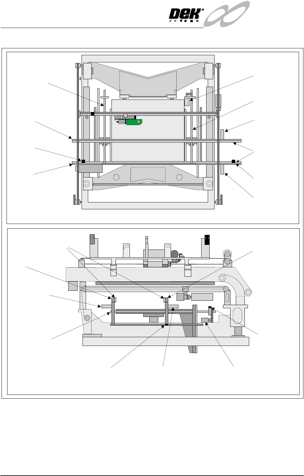
Figure 15-1 Rail System Overview
FixedRail
Motorized Rail
BoardTransportBelts
Motorized Rail
DriveShaft
FrontTransport
Belt Motor
Rear Transport Belt Motor
Rail Lifted Left Sensor
(Right Hand Side Similar)
Moving Rail DriveMotor
Rail Home
Sensor
BoardTransport
Belt Drive Motor
8M04
BoardTransport
Belt Drive Motor
8M03
BoardTransport
Belts
Boardat Right
Sensor
Boardat Left
Sensor
Moving Rail
FixedRail
Moving Rail
DriveMotor
8M02
Moving Rail DriveShaft
Moving Rail
DriveShaft
Plan View on Machine - Printhead Removed
View on Right Hand Side of Machine
PULNIX
TM-6EX
INFINITY
EX
RAIL SYSTEM MODULE
MODULE SCHEMATIC
Chapter Issue 2 Jan 04 Technical Reference Manual 15.3
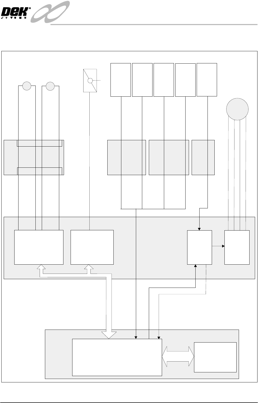
MODULE SCHEMATIC
Breakout D
DPL1 DSK5
Machine PC
NextMove
Processor
ISA
BUS
CAN BUS
MUX Axis Home
Machine Controller
Front Belt
Drive
(8M03)
24V dc Motors
Rear Belt
Drive
(8M04)
8M2
Moving Rail
Stepper
Home
Motor 2B-
Motor 2A-
Motor 2B+
Motor 2A+
Stepper Direction
Breakout C
M
M
Board Clamp/
Snugger Solenoid
(16SOL10)
Source 3
Totem 0 (Fwd)
Totem 1 (Rev)
Totem 2 (Fwd)
Totem 3 (Rev)
CSK7
CSK2
Manual Operation
Board at Right
Sensor
(8SE7)
Board at Left
Sensor
(8SE8)
Rail Lift
Right
(8SE4)
Rail Lift
Left
(8SE5)
DIG IN 16
DIG IN 17
Breakout B
BPL1 BSK3
Breakout A
APL1 ASK4
DIG IN 3
DIG IN 4
Stepper
Multiplexer
MultiMove
(X12)
MultiMove
(X13)
Moving Rail
Home
(8SE6)
Dual Stepper
X4
INFINITY
EX
RAIL SYSTEM MODULE
MECHANICAL DETAIL
15.4 Technical Reference Manual Chapter Issue 2 Jan 04
MECHANICAL DETAIL
Belt Drive The board is transported on ‘O’ ring type belting which is driven by two moving
coil motors, one on each rail.
The speed of these motors is controlled by a MultiMove card in the machine
controller which can be adjusted via the machine diagnostics (Belt Speed
Calibration page).
NOTE
For belt speed calibration refer to the Calibrations Section of this chapter.
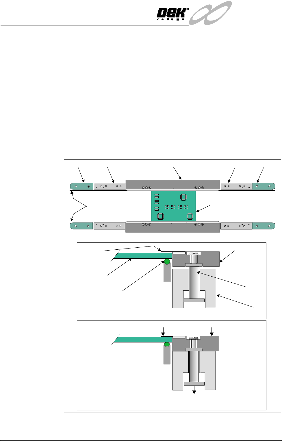
Board Clamps A board clamping arrangement is utilized to minimize board distortion during
print process. A pneumatically operated piston, (via a 24v switched solenoid
16SOL10 from the machine controller), lowers the board clamp and foil trapping
the board on the transport belts. On completion of the print stroke the board is
released by activation of the pneumatic solenoid.
Figure 15-2 Board Clamping Arrangement
Transport Belts
Pneumatic Piston Driven Downwards
WARNING-SHARP EDGE
PATENT No.5157438
End Rail End RailMid Rail Mid RailBoard Clamp
Board
Board Trapped Between Foil and Transport Belt
Plan View of Rail System
Transport Belt
Rail
Piston
Metal Foil
Board Clamp
Board
Board Free on Transport Belt
Board Clamp and Foil Lowered
WARNING-SHARP EDGE
PATENT No.5157438