Infinity EX Rail System Module.pdf - 第6页
INFINITY EX RAIL S YSTEM M ODULE MECHANICAL DETA IL 15.6 Technical Reference Manu al Chapter Is sue 2 Jan 04 F oil-less Clamps This option is used on thin boards which are populated with components too close to the edge …
INFINITY
EX
RAIL SYSTEM MODULE
MECHANICAL DETAIL
Chapter Issue 2 Jan 04 Technical Reference Manual 15.5
Board Snugger
Assembly
The board snugger assembly is an alternative option to the standard board clamp
arrangement. This feature is utilized when there is a requirement to print close
to the board edge.
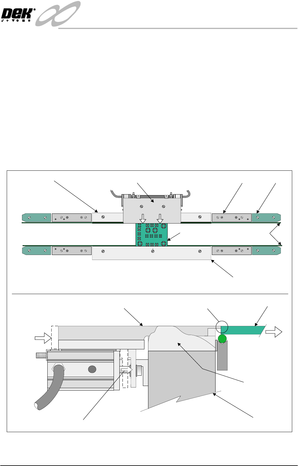
The adjustable snugger plate, rear rail guide and fixed snugger plates are
interchangeable with similar units to facilitate differences in board thickness.
This system caters for 0.8mm, 1.0mm and 1.6mm board thickness.
To clamp the board in position for the printing process, the board is gripped
between the fixed and adjustable snugger plates by action of the pneumatically
operated piston (figure below refers). Pneumatic operation utilizes the existing
board clamp circuit, (via a 24v switched solenoid 16SOL10 from the machine
controller).
On completion of the print stroke the pneumatic solenoid is de-activated allow-
ing the actuator pistons (sprung loaded), to retract the adjustable snugger plate
away from the board.
Figure 15-3 Board Snugger Clamping Arrangement
Transport Belts
End RailMid Rail
Board
Fixed Rail
Moving Rail
I.O
Adjustable Snugger Plate
Fixed Snugger Plate
Plan View of Rail System (Showing Board Clamped)
Rear Rail Guide
Board Clamping Action
Pneumatic Piston Extended
Board
Moving Rail
Movement of Adjustable
Snugger Plate
Movement
of Board
Rear Rail Guide
(Cutaway View)
Adjustable Snugger Plate Board Gripped by Snugger Plate
INFINITY
EX
RAIL SYSTEM MODULE
MECHANICAL DETAIL
15.6 Technical Reference Manual Chapter Issue 2 Jan 04
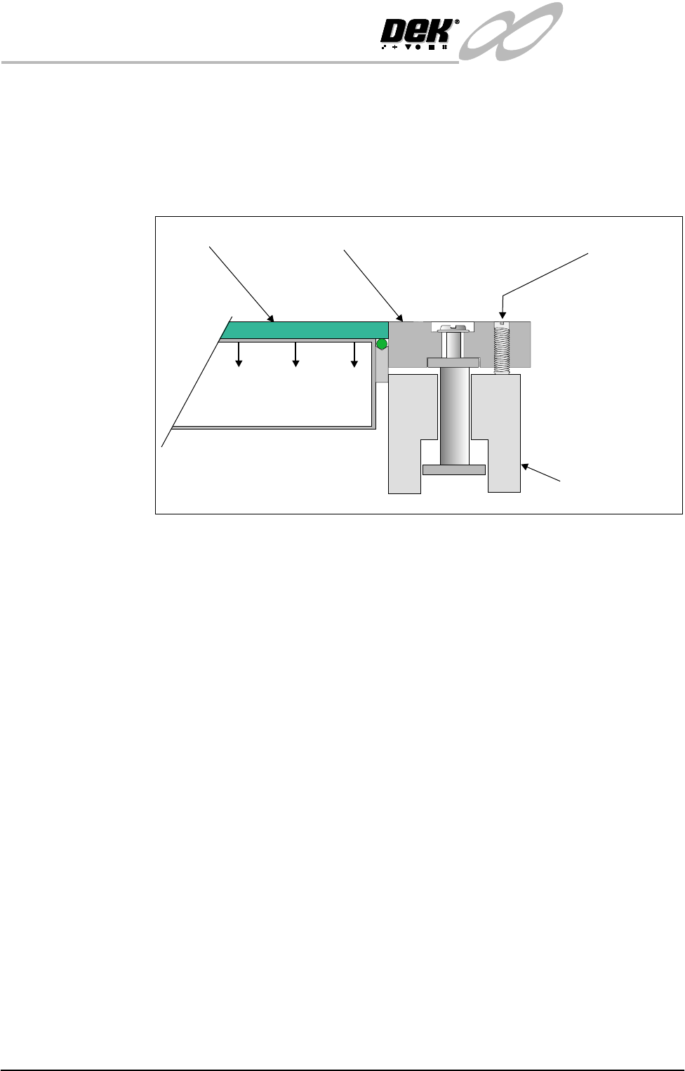
Foil-less Clamps This option is used on thin boards which are populated with components too
close to the edge of the board for traditional board clamps. The board is secured
during the print stroke by the use of vacuum. The clamps are perpendicular to
the board maintaining a good gasket between the board and the stencil. The
clamps are adjusted in height for different thicknesses of board by two grub
screws.
Figure 15-4 Side View of Foil-less Clamp Operation
Adjustment Grub Screw
Rail
Foil-less ClampBoard
Vacuum Box
INFINITY
EX
RAIL SYSTEM MODULE
DRIVES AND SENSORS
Chapter Issue 2 Jan 04 Technical Reference Manual 15.7
DRIVES AND SENSORS
Sensors
Motors
NOTE
Location of rail system sensors and drives are detailed on the Rail System
Overview Figure at the beginning of this chapter.
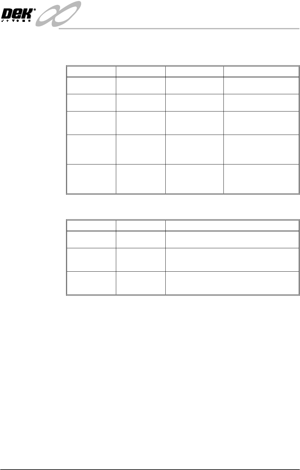
Name Type Test Point Functional Description
Rail Lifted Left Through Beam
Opto
NextMove Dig IN 3 Detects premature lifting of
rail
Rail Lifted Right Through Beam
Opto
NextMove Dig IN 4 Detects premature lifting of
rail
Moving Rail
Home
Through Beam
Opto
Stepper Multiplexer
MUX2
Provides home position of
moving rail thus providing
accurate board width settings
Board at Left Diffuse Opto NextMove Dig IN 16 Detects left side incoming/
outgoing board dependent
upon machine pass through
configuration
Board at Right Diffuse Opto NextMove Dig IN 17 Detects right side incoming/
outgoing board dependent
upon machine pass through
configuration
Name Type Functional Description
Moving Rail
Drive
Stepper Motor Moves the rear moving rail in the Y direction
Front Board
Transport Belt
Drive
DC Moving Coil
Motor
Turns the front transport belt in the clockwise or anti
clockwise direction (dependent upon upline/down-
line feed direction)
Rear Board
Transport Belt
Drive
DC Moving Coil
Motor
Turns the rear transport belt in the clockwise or anti
clockwise direction (dependent upon upline/down-
line feed direction)