197052.pdf - 第17页
Features QS18 Series Sensor Product Manual 01-Jun-26 page 17 of 29 © Banner Engineering Corp. All rights reserved. www .bannerengineering.com Bifurcated - Glass Fiber (Performance is based on a 90% reflectance white t…
FeaturesQS18 Series Sensor Product Manual
01-Jun-26page16of29 © Banner Engineering Corp. All rights reserved.
www.bannerengineering.com
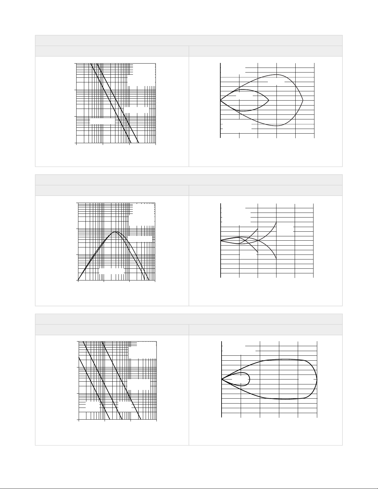
Opposed - Plastic Fiber
Excess Gain Curve Beam Pattern
1
10
100
10 mm
.40 in
100 mm
4.0 in
1000 mm
40 in
1 mm
.04 in
1000
Excess Gain
Distance
QS18..FP
QS18..FP
Opposed Mode
Plastic Fibers
PIT66U Fiber
PIT46U Fiber
250 mm
10 in
200 mm
8 in
150 mm
6 in
100 mm
4 in
50 mm
2 in
0
0
20 mm
40 mm
60 mm
20 mm
40 mm
60 mm
0
0.8 in
1.6 in
2.4 in
0.8 in
1.6 in
2.4 in
Distance
QS18..FP
QS18..FP
PIT46U
PIT66U
Opposed Mode
Plastic Fibers
Bifurcated - Plastic Fiber (Performance is based on a 90% reflectance white test card.)
Excess Gain Curve Beam Pattern
1
10
100
1 mm
.04 in
10 mm
.4 in
100 mm
4 in
.1 mm
.004 in
1000
Excess Gain
Distance
Diffuse Mode
Plastic Fibers
PBT66U Fiber
PBT46U Fiber
QS18..FP
QS18..FP
100 mm
4.8 in
80 mm
3.2 in
60 mm
2.4 in
40 mm
1.6 in
20 mm
0.8 in
0
0
10 mm
20 mm
30 mm
10 mm
20 mm
30 mm
0
0.4 in
0.8 in
1.2 in
0.4 in
0.8 in
1.2 in
Distance
QS18..FP
QS18..FP
PBT46U
PBT66U
Diffuse Mode
Plastic Fibers
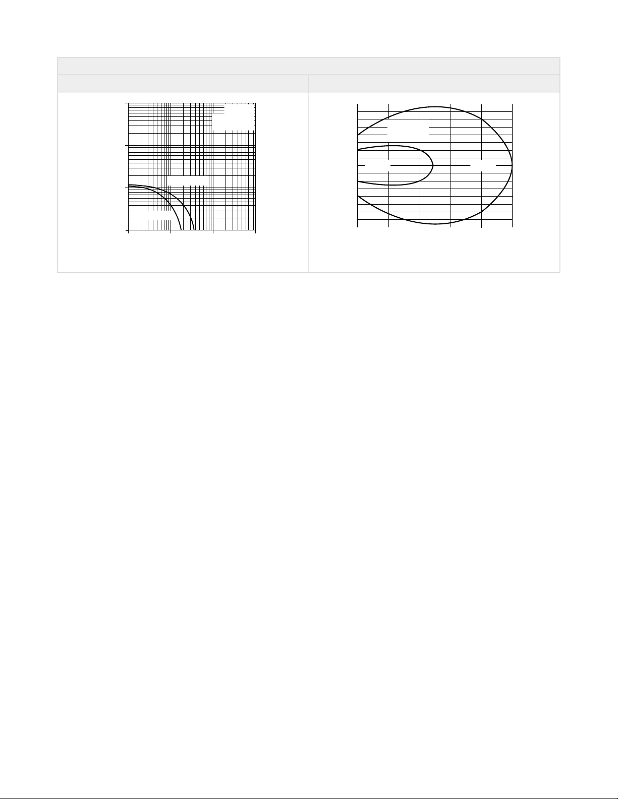
Opposed - Glass Fiber (Performance is based on a 90% reflectance white test card.)
Excess Gain Curve Beam Pattern
1
10
100
.1 m
.33 ft
1 m
3.3 ft
10 m
33 ft
.01 m
.033 ft
1000
Excess Gain
Distance
QS18F
Opposed Mode
Glass Fibers
IT23S Fibers
w/L9 lenses
IT23S
Fibers
IT13S
Fibers
500 mm
20 in
400 mm
16 in
300 mm
12 in
200 mm
8 in
100 mm
4 in
0
0
25 mm
50 mm
75 mm
25 mm
50 mm
75 mm
0
1 in
2 in
3 in
1 in
2 in
3 in
Distance
QS18F
Opposed Mode
IT13S IT23S
Features QS18 Series Sensor Product Manual
01-Jun-26 page17of29© Banner Engineering Corp. All rights reserved.
www.bannerengineering.com
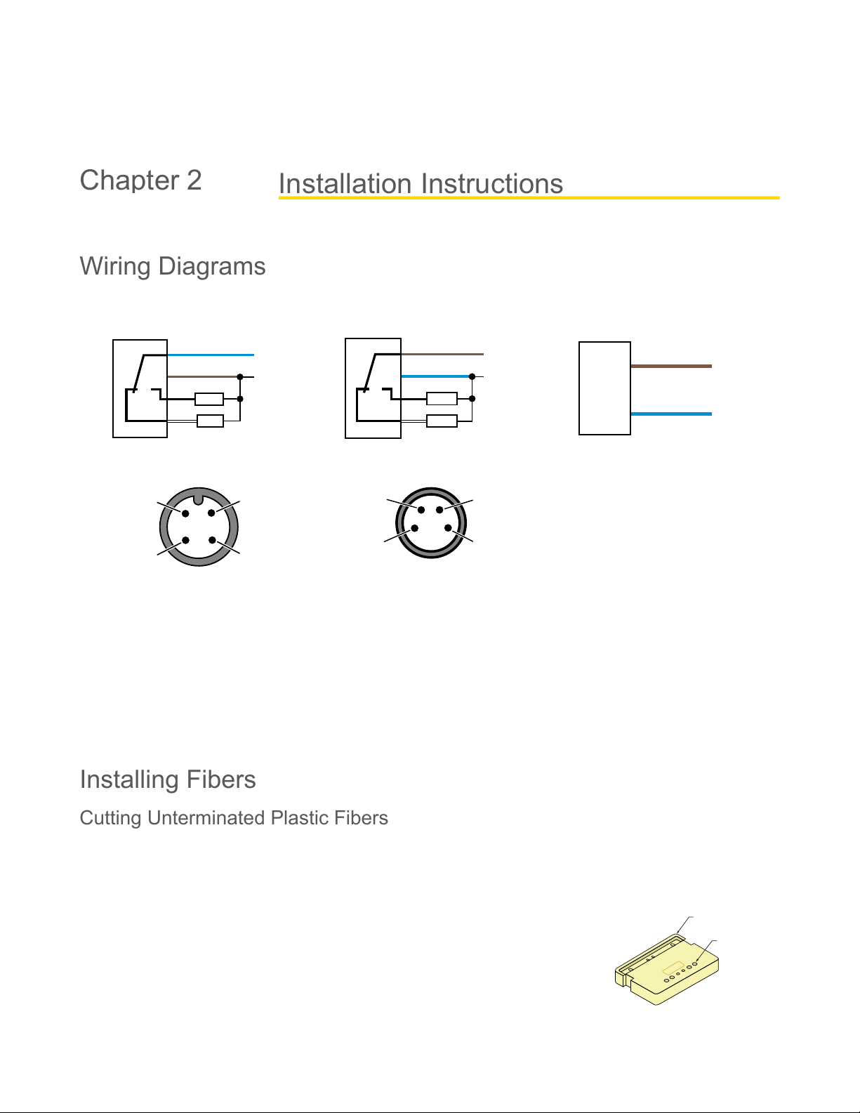
Bifurcated - Glass Fiber (Performance is based on a 90% reflectance white test card.)
Excess Gain Curve Beam Pattern
1
10
100
10 mm
.4 in
100 mm
4 in
1000 mm
40 in
1 mm
.04 in
1000
Excess Gain
Distance
QS18F
Diffuse Mode
Glass Fibers
BT23S Fiber
BT13S Fiber
37.5 mm
1.5 in
30 mm
1.2 in
22.5 mm
0.9 in
15 mm
0.6 in
7.5 mm
0.3 in
0
0
0.65 mm
1.3 mm
1.9 mm
0.65 mm
1.3 mm
1.9 mm
0
0.025 in
0.050 in
0.075 in
0.025 in
0.050 in
0.075 in
Distance
QS18F
Diffuse Mode
BT23SBT13S
01-Jun-26 page18of29
QS18 Series Sensor Product Manual
© Banner Engineering Corp. All rights reserved.
www.bannerengineering.com
•
•
•
•
•
PFC-1 Cutting Device
Cutting Ports
Lift to Open Ports
Chapter Contents
Wiring Diagrams................................................................................................................................................................................................. 18
Installing Fibers .................................................................................................................................................................................................. 18
Mount the Device ............................................................................................................................................................................................... 20
Wiring Diagrams
QS18 with NPN outputs
10-30 V DC
–
+
bn (1)
bu (3)
wh (2)
bk (4)
Load
Load
Dark operate
Light operate
QS18 with PNP outputs
10–30 V DC
–
+
bn (1)
bu (3)
wh (2)
bk (4)
Load
Load
Dark operate
Light operate
QS18 Emitters
10–30 V DC
–
+
bn (1)
bu (3)
4-pin M12 male pinouts
1
2
3
4
4-pin M8 male pinouts
4
31
2
1 = Brown
2 = White
3 = Blue
4 = Black
In dark operate (DO) mode, the output is ON when the target returns less light to the sensor than the configured target and
OFF when the sensor detects more light than the configured/taught target.
In light operate (LO) mode, the output is ON when the target returns the same or more light to the sensor and OFF when the
sensor detects less light than the configured/taught target.
In opposed and retroreflective sensing modes, light operate is active when the beam is unblocked and dark operate is active
when the beam is blocked.
In diffuse and fixed field sensing modes, light operate is active when the target is present and dark operate is active when the
target is absent.
Installing Fibers
Cutting Unterminated Plastic Fibers
Unterminated plastic fibers are designed to be cut by the user to the length required for the application.
To facilitate cutting, a Banner model PFC-1 cutting device is supplied with the fiber. Cut the
fiber as follows:
Use small ports for fiber sizes:
0.25 mm (0.01 inches)
0.5 mm (0.02 inches)
Use large ports for fiber sizes:
0.75 mm (0.03 inches)
1.0 mm (0.04 inches)
1.5 mm (0.06 inches)
Installation Instructions
Chapter 2