197052.pdf - 第19页
Installation Instructions QS18 Series Sensor Product Manual 01-Jun-26 page 19 of 29 © Banner Engineering Corp. All rights reserved. www .bannerengineering.com Install the Plastic Fibers Follow these steps to install t…
01-Jun-26 page18of29
QS18 Series Sensor Product Manual
© Banner Engineering Corp. All rights reserved.
www.bannerengineering.com
•
•
•
•
•
PFC-1 Cutting Device
Cutting Ports
Lift to Open Ports
Chapter Contents
Wiring Diagrams................................................................................................................................................................................................. 18
Installing Fibers .................................................................................................................................................................................................. 18
Mount the Device ............................................................................................................................................................................................... 20
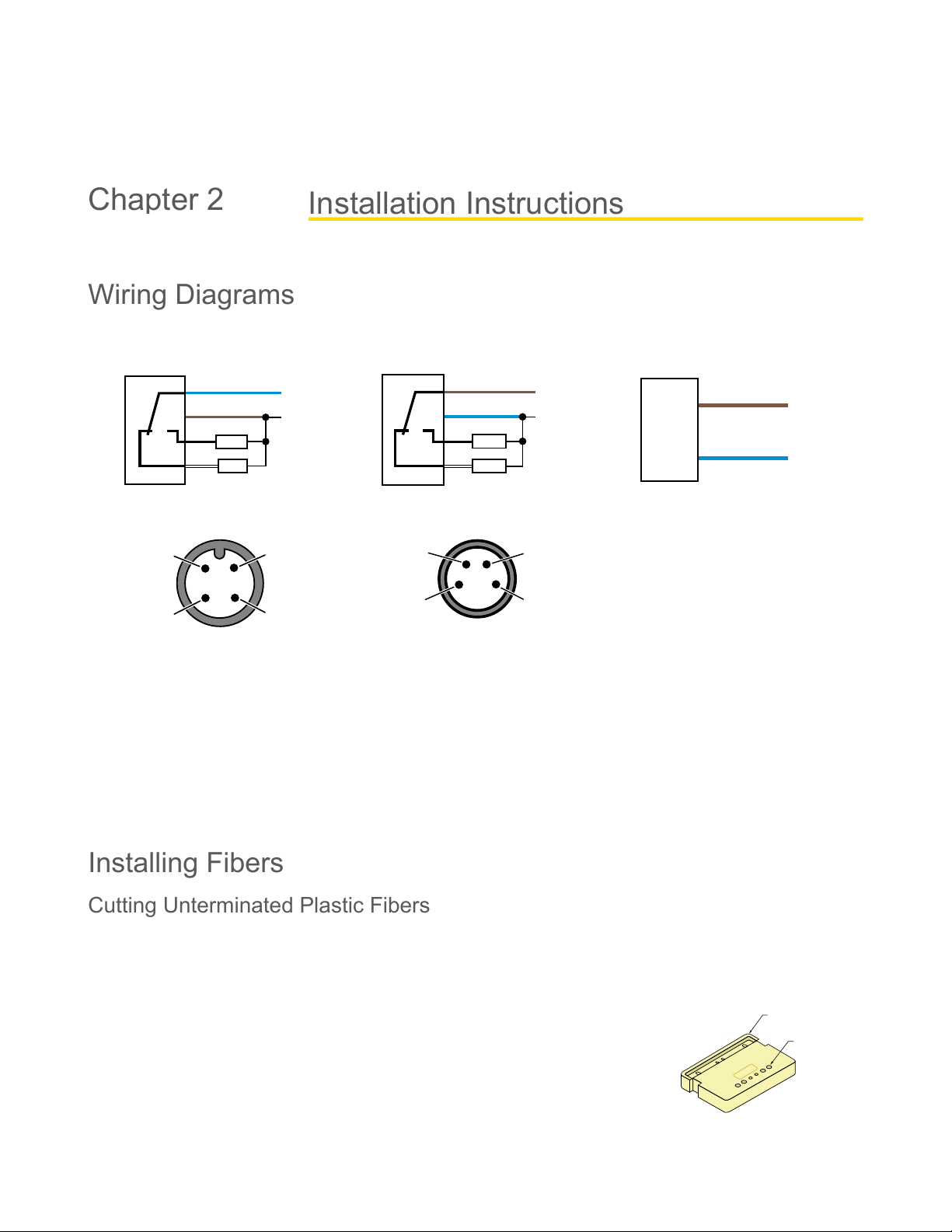
Wiring Diagrams
QS18 with NPN outputs
10-30 V DC
–
+
bn (1)
bu (3)
wh (2)
bk (4)
Load
Load
Dark operate
Light operate
QS18 with PNP outputs
10–30 V DC
–
+
bn (1)
bu (3)
wh (2)
bk (4)
Load
Load
Dark operate
Light operate
QS18 Emitters
10–30 V DC
–
+
bn (1)
bu (3)
4-pin M12 male pinouts
1
2
3
4
4-pin M8 male pinouts
4
31
2
1 = Brown
2 = White
3 = Blue
4 = Black
In dark operate (DO) mode, the output is ON when the target returns less light to the sensor than the configured target and
OFF when the sensor detects more light than the configured/taught target.
In light operate (LO) mode, the output is ON when the target returns the same or more light to the sensor and OFF when the
sensor detects less light than the configured/taught target.
In opposed and retroreflective sensing modes, light operate is active when the beam is unblocked and dark operate is active
when the beam is blocked.
In diffuse and fixed field sensing modes, light operate is active when the target is present and dark operate is active when the
target is absent.
Installing Fibers
Cutting Unterminated Plastic Fibers
Unterminated plastic fibers are designed to be cut by the user to the length required for the application.
To facilitate cutting, a Banner model PFC-1 cutting device is supplied with the fiber. Cut the
fiber as follows:
Use small ports for fiber sizes:
0.25 mm (0.01 inches)
0.5 mm (0.02 inches)
Use large ports for fiber sizes:
0.75 mm (0.03 inches)
1.0 mm (0.04 inches)
1.5 mm (0.06 inches)
Installation Instructions
Chapter 2
Installation Instructions QS18 Series Sensor Product Manual
01-Jun-26 page19of29© Banner Engineering Corp. All rights reserved.
www.bannerengineering.com
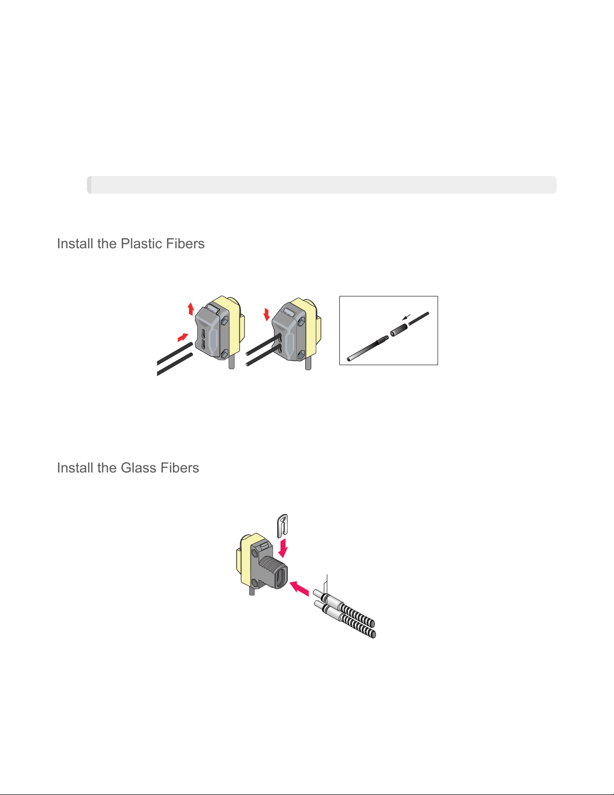
Install the Plastic Fibers
Follow these steps to install the plastic fibers.
Installing Plastic Fibers
A
B
C
Fiber end
Adapter
Adapter Installation
Install the Glass Fibers
Follow these steps to install the glass fibers.
Installing the glass fibers in a QS18 sensor
O-rings
Retaining Clip
Locate the control end of the fiber (the unfinished end).
1.
Determine the length of fiber required for the application. If using a bifurcated fiber, separate the two halves of the
fiber at least 51 mm (2 inches) beyond the fiber-cutting location.
2.
Lift the top (blade) of the cutter to open the cutting ports.
3.
Insert one of the control ends through one of the cutting ports on the cutter so that the excess fiber protrudes from the
back of the cutter.
4.
Double-check the fiber length, and close the cutter until the fiber is cut.
5.
Using a different cutting port, cut the second control end to the required length.
NOTE: To ensure a clean cut each time, do not use a cutting port more than once.
6.
Gently wipe the cut ends of the fiber with a clean, dry cloth to remove any contamination. Do not use solvents or
abrasives on any exposed optical fiber.
7.
Slide the fiber gripper up to unlock it (A).
1.
If using 0.25 mm or 0.5 mm core fibers, slide the plastic fiber adapters onto the fibers, flush with the fiber ends.
2.
Carefully insert the prepared plastic fiber ends into the ports (B) as far as possible without applying extra force.
3.
Slide the fiber gripper down to lock the fibers in place (C).
4.
Slide the supplied o-ring on the sensor end of the fibers, as shown.
1.
Press the fiber ends firmly into the ports located on the front of the sensor.
2.
Slidethesuppliedu-shapedretainingclipintotheslotinthesensor’sbarreluntiltheclipsnapsintoplace.
3.

Installation InstructionsQS18 Series Sensor Product Manual
01-Jun-26page20of29 © Banner Engineering Corp. All rights reserved.
www.bannerengineering.com
Mount the Device
If a bracket is needed, mount the device onto the bracket.
1.
Mount the device (or the device and the bracket) to the machine or equipment at the desired location. Do not tighten
the mounting screws at this time.
2.
Check the device alignment.
3.
Tighten the mounting screws to secure the device (or the device and the bracket) in the aligned position.
4.