cab_products_electronic_industry.pdf - 第12页
1 7 mm 12 T o be equipped both in vertical and horizontal orientation The system' s variable width enables individual assembly acc ording to any PCB size. Magazines 100, 180 and 300 mm in height are o ered for the …
0...40 70
630...22
10°
11
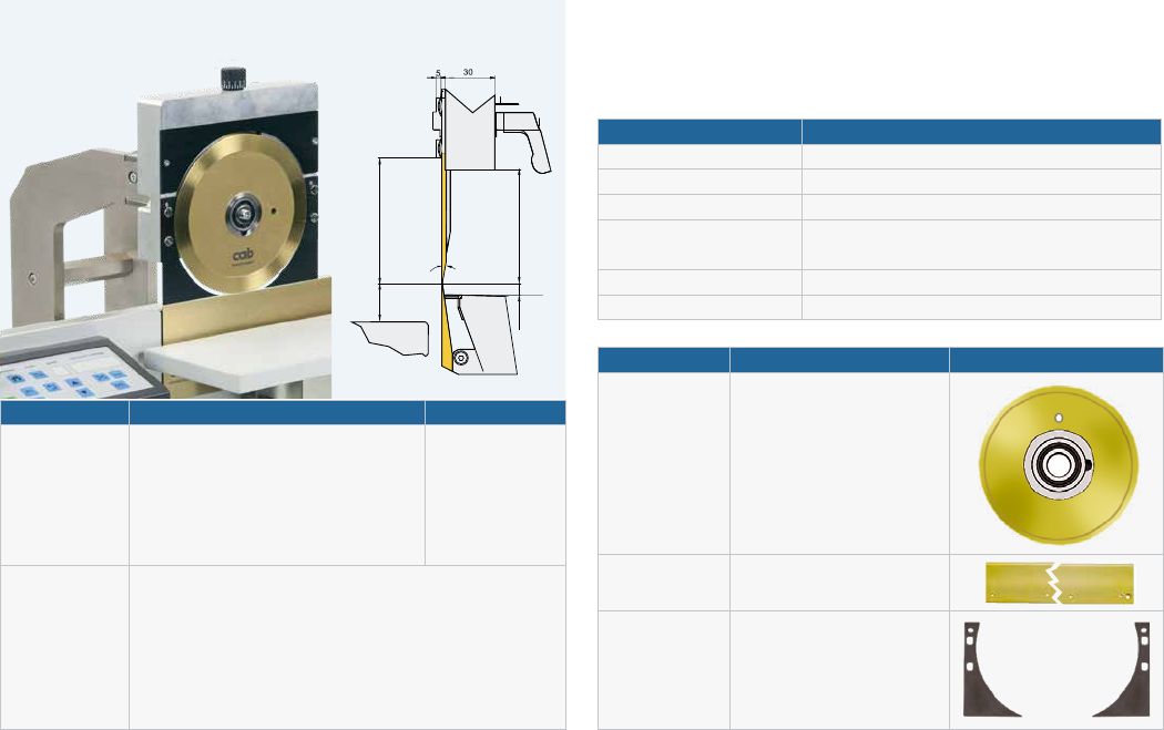
PCB separator MAESTRO 6
MAESTRO 6/601.70
Separation of FR4 and CEM3 PCBs up to lengths of 600 mm
and component heights of 70 mm; further lengths on request
Technical data 6/601.70
Circular blade diameter 185 mm
Separation speed up to 500 mm/s
Materials FR4, CEM3
Component height Component side up to 63 mm
Solder side up to 22 mm
Width x Height x Depth 1,150 x 410 x 450 mm
Weight 50 kg
Part no. Product Sep. length
8936590 PCB separator MAESTRO 6/601.70 up to 600 mm
Scope
of delivery
PCB separator
Power cable Type E+F, length 1.8 m
Foot switch
Allen key 2 mm
Dial gauge
Operator's manual DE/EN
Part no. Wear parts
8933933.001 Circular blade 185
8936593.001
8936592.001
Linear blade 450
Linear blade 600
8936583.001
8936584.001
Blade protection 1 X01/70
Blade protection 2 X01/70
17 mm
12
To be equipped both in vertical and horizontal orientation
The system's variable width enables individual assembly
according to any PCB size.
Magazines 100, 180 and 300 mm in height
are oered for the various PCBs.
32 slots in gaps of of 10 mm oer maximum packing density.
Safe guidance
Funnel-shaped slot entries ensure safe PCB insertion.
Yellow position stickers indicate the exact positions
and prevent from falsely inserting PCBs diagonally by hand.
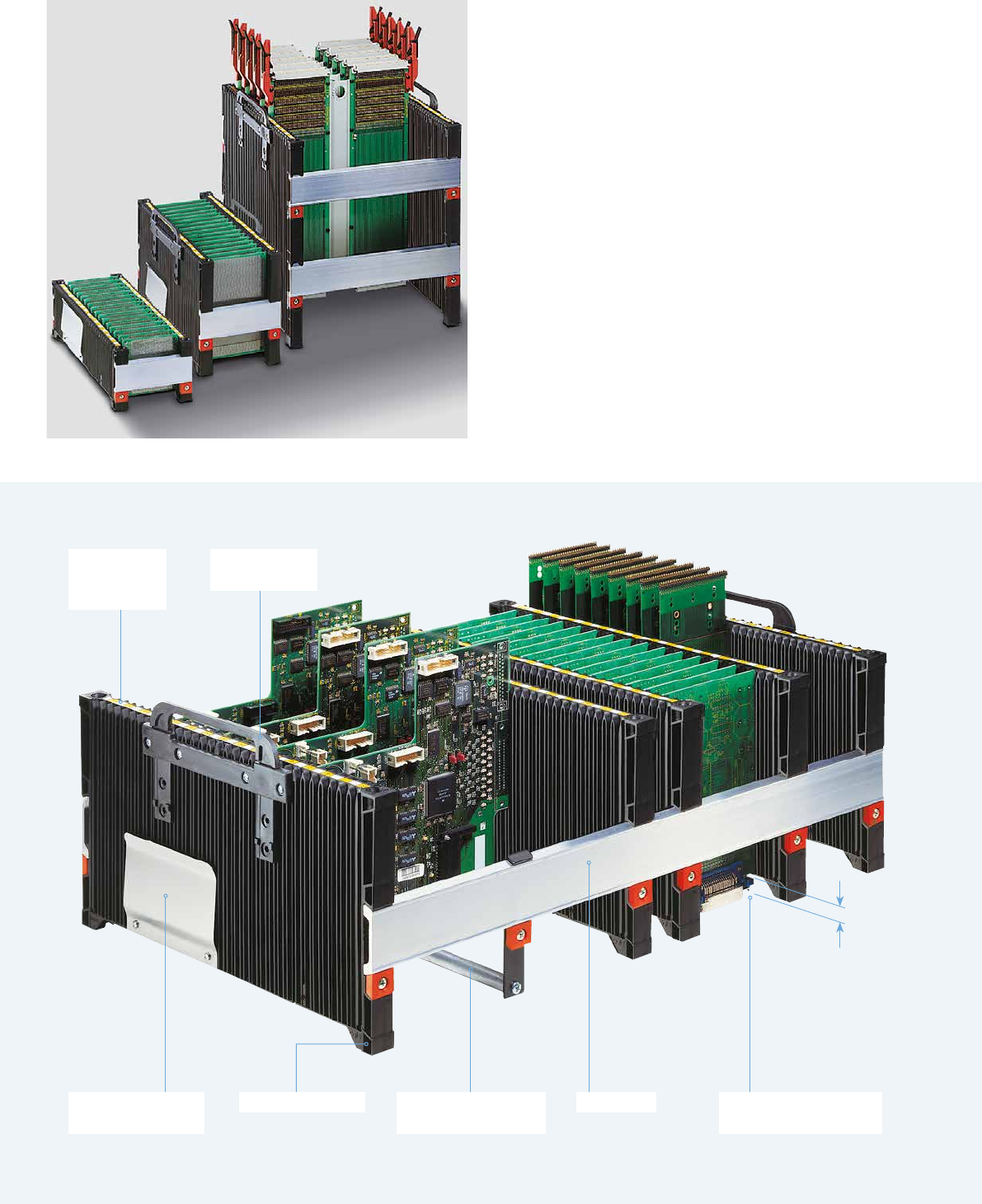
PCB magazine series 100, 180, 300
Consecutive
numbers
and markings
Carry handle
to be retracted
Bracket for accom-
panying documents
Support rail
to secure heavy PCBs
Prole rail
Free space to protect
protruding components
Doubled side wall
providing 32 PCB slots
x = 36 + D1 x = 52 + D1 + D2 x = 69 + D1 + D2 + D3 x ≥ 73 + D1 + D2 x ≥ 110 + D1 + D2 + D3
13
PCB magazine series 100, 180, 300
Technical data 100 180 300
Material Polypropylene
Color black
Surface resistance accord. to DIN EN 61340-5-1 < 10
9
Slot width 2.8 mm 4 mm 3.5 mm
Slot depth 2 mm 2.5 mm 2.5 mm
Number of slots 32
Distance between the PCBs 10 mm
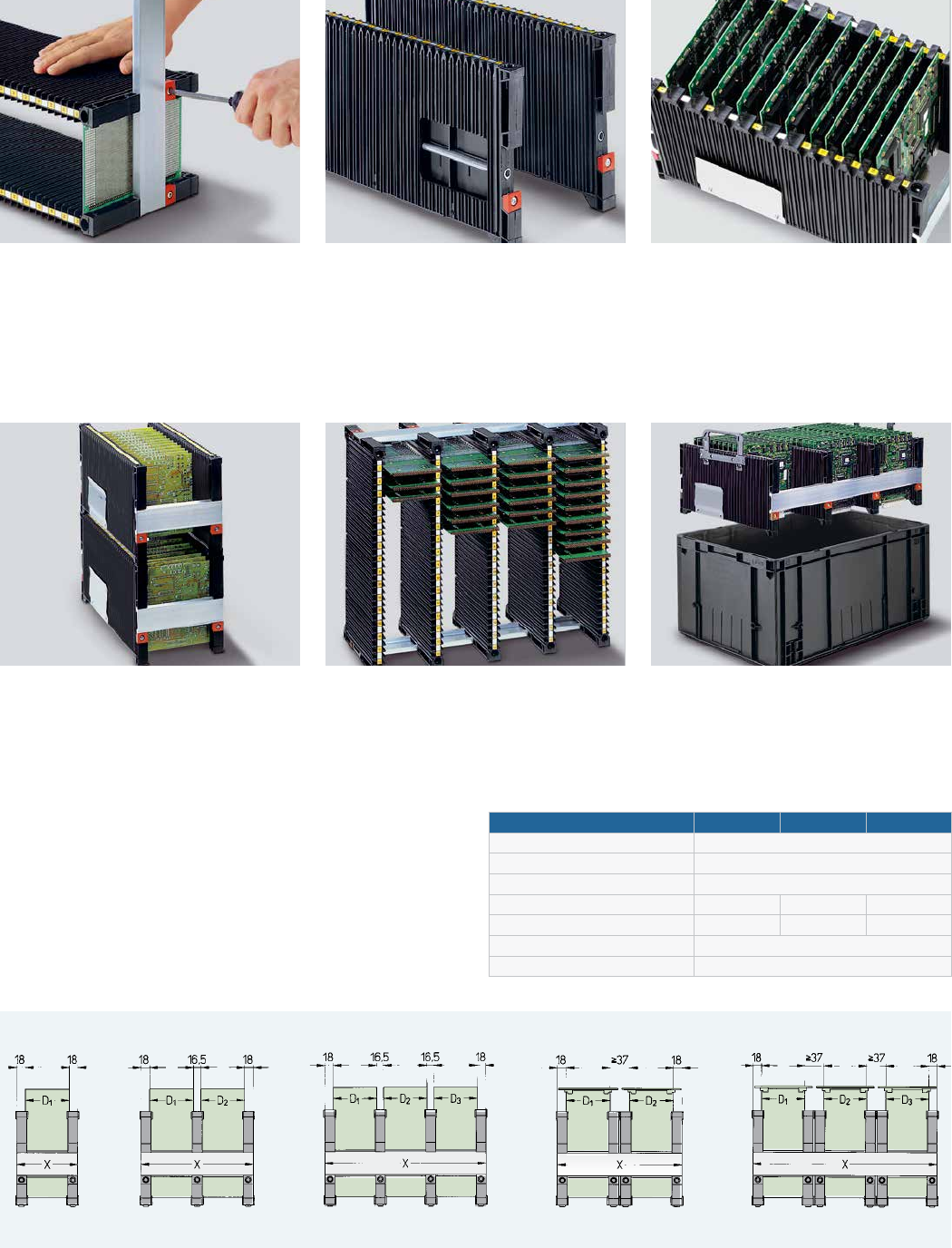
Length of prole rails D = PCB width x = prole rail width
Quick and simple assembly
The side walls are adjustable with the help
of the prole rails. Two PCBs are inserted
in the outer adjusting grooves. The upper
side wall has to be pressed against the PCBs
and be xed with screws.
Solid and resistant to torsion
The double-wall construction makes the
side walls extremely solid. A metal tube is
provided to further stien a side wall in the
case of high mechanic and thermal forces.
Slot lock
To prevent from component damage
when inserting PCBs in a magazine,
slots that are not in use can be covered.
Stackable
Boreholes and pins on the outer margins
allow the magazines to be stacked.
On the bottom of the side walls, molded
recesses simplify the liing.
Upright position
Assembled PCBs need horizontal storage
before soldering. For this purpose,
the magazines are set upright.
Transport boxes
The magazines can be inserted into
standard 600 x 400 resp. 400 x 300 mm
boxes for transport. Retractable carry
handles simplify the insertion and removal.