00192368-01.pdf - 第34页
Vacuum Tooling for HS-50 Retrofit Instructions / User Manual 3 Functional Description Edition 12/00 34 The solen oid va lve (of the option) sw itches on the va cuum. – The lifting table c ontinues to move upwa rd. The va…
Retrofit Instructions / User Manual Vacuum Tooling for HS-50
Edition 12/00 3 Functional Description
33
3 Functional Description
This option uses suction to pick up PCBs 8.5” wide and of various lengths and to hold them pre-
cisely and level on a vacuum plate (tool top plate of vacuum tooling) during the placement pro-
cess. This establishes optimal conditions for placement.
The tool of the “vacuum tooling” is supplied by the Motorola Company.
During commissioning, Siemens makes the compressed air connection and integrates the elec-
trical system into the machine.
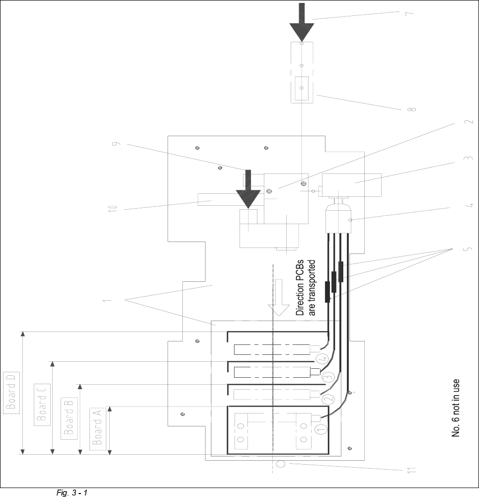
The most important functional elements of this option (see Fig. 3 - 1) are
– the tool (consisting of top and bottom plate) on the bottom plate which is placed in a defined
position (see Section 5.1) on the lifting table and held in place there by magnets. Depending
on the model from Motorola, the tool delivered is an 8.5” or an 11” type.
– the vacuum generator to which a number of vacuum branches are connected via multiple dis-
tributors (number varies by tooling model):
The vacuum generator is supplied with 5.5 bar compressed air from the compressed air unit
inside the machine.
The vacuum branches can be connected or disconnected, either manually via shut-off cocks
or automatically by appropriate shut-off valves (varies by model).
– the 3/2-way solenoid valve to shut the vacuum to the option ON and OFF during the place-
ment. process.
– the compressed air interface to connect the option’s vacuum generator to the 5.5 bar compres-
sed air branch inside the machine.
- the "vacuum tooling drive" for conveyor 1 and possibly for conveyor 2 (I/O terminal panel: see
Fig. 3 - 2):
– the electrical interface to connect the option to the power supply / drive:
– When the option is installed, it must also be connected electrically (see Section 5).
– The width adjustment is not deactivated and the optional sequence “vacuum tooling” for fa-
stening the PCB in place are not possible until after this electrical connection is made.
7KHYDFXXPWRROLQJVHTXHQFHLVGLYLGHGLQWRVHF WL RQV
0RYH3&%LQDQGKROGLWLQSODFHZLWKVXFWLRQ
– The PCB moves to the placement area 1 - 4 -> The sonar proximity switch reports “PCB
present” -> The conveyor speed is reduced -> The stopper which has extended in the inte-
rim positions the PCB in the transport direction -> The lifting table starts moving upward ->
Vacuum Tooling for HS-50 Retrofit Instructions / User Manual
3 Functional Description Edition 12/00
34
The solenoid valve (of the option) switches on the vacuum.
– The lifting table continues to move upward. The vacuum plate of the option is pressed
against the PCB below with a spring action.
– The lifting table reaches the “Top” position -> The PCB is sucked against the suction cups.
It is now level and is held in place on the top plate -> The placement process begins.
6ZLWFKRIIWKHYDFXXPDQGPRYHRXWWKH3&%
– Placement is over, the PCB is still clamped in the conveyor and the vacuum is on
-> The signal "Lifting table down" is issued.
– The solenoid valve switches the vacuum off.
– When the time interval for "Vacuum reduced" is reached, the lifting table moves down with
the vacuum plate.
– The proximity switch "Lifting table down" is activated -> the PCB is transported into the un-
loader.
6HWWLQJWKH7LPH,QWHUYDOIRU9DFXXP5HGXFWLRQ
– Connect the keyboard to the machine controller.
– Place the boot diskette into the machine controller disk drive.
– Turn on the main switch of the placement system.
– The time interval is displayed and may be edited
Input range 0 ... 2000ms
Default value 750 ms
Key to the following illustrations:
1 Tool with bottom plate of the option
2 Solenoid valve(s)
3 Vacuum generation (varies by model)
4 Multiple distributor for vacuum branches
5 Shut-off cock or shut-off valves for vacuum branches
6 Y-connector (2)
7 Compressed air interface: connection to the 5.5 bar compressed air branch inside the machine
8 Plug-in connector for compressed air
9 Interface for electricity: connection to the power supply / option’s drive
10 Silencer
11 PCB conveyor stopper
Retrofit Instructions / User Manual Vacuum Tooling for HS-50
Edition 12/00 3 Functional Description
35
General View of the Option “Vacuum Tooling, Motorola Company”, (Top View)