00192368-01.pdf - 第37页
Retrofit Instructions / User Manual Vacuum Tooling for HS-50 Edition 12/00 4 Instal ling the compressed air supply 37 ,QVW D OOLQJWKHFRPSUHVVH GDLUVXSSO\ : Move the componen t cart for gantry 1 o ut of the pl aceme…
Vacuum Tooling for HS-50 Retrofit Instructions / User Manual
3 Functional Description Edition 12/00
36
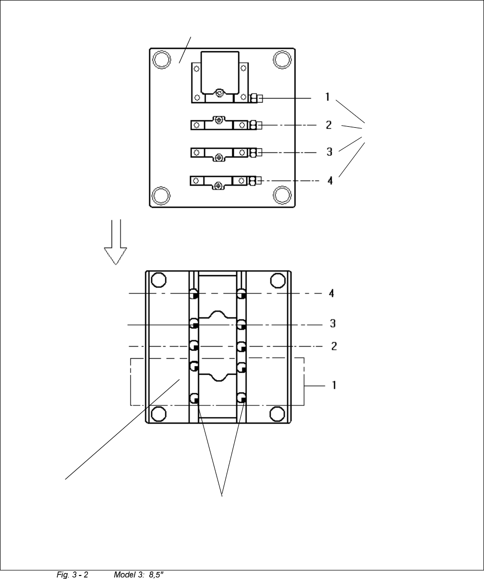
Suction cups
(bottom view)
Top plate of tool
Connection
for vacuum
branches
Direction PCBs
are transported in
Top plate of tool
(top view)
Retrofit Instructions / User Manual Vacuum Tooling for HS-50
Edition 12/00 4 Installing the compressed air supply
37
,QVWD OOLQJWKHFRPSUHVVH GDLUVXSSO\
:
Move the component cart for gantry 1 out of the placement machine.
:
Detach the waste tape chute.
:
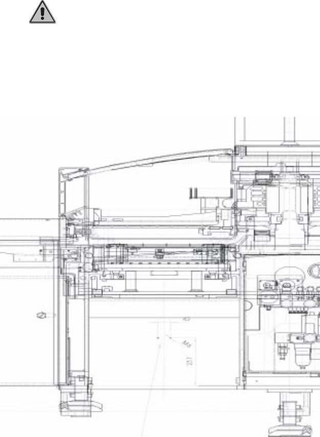
At placement area 1, drill two Ø 5 mm holes in the wall behind the waste tape chute.
The precise position is shown in the drawing.
____________________________________________________________________________
PLEASE NOTE
!
Drill only to a depth of 10 mm. Do not drill right through the wall, otherwise the cables behind the
wall may be damaged.
___________________________________________________________________________
Vacuum Tooling for HS-50 Retrofit Instructions / User Manual
4 Installing the compressed air supply Edition 12/00
38
:
Tap an M6x8 thread in the hole.
:
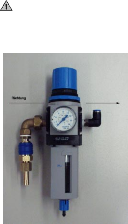
Assemble the compressed air maintenance unit (see photograph below).
The compressed air flows from left to right.
____________________________________________________________________________
PLEASE NOTE
!
Make sure that the air flows through the compressed air maintenance unit in the correct
direction.
___________________________________________________________________________
: Use two M6 x 8 fillister head screws to fix the bracket.
Place the compressed air maintenance unit (see photograph below) on the bracket.