00192368-01.pdf - 第40页
Vacuum Tooling for HS-50 Retrofit Instructions / User Manual 4 Installing the compressed air supply Edition 12/00 40 : Connect the four va cuum tooling hoses to the compr essed air d istributor . : Refit the was te t…
Retrofit Instructions / User Manual Vacuum Tooling for HS-50
Edition 12/00 4 Installing the compressed air supply
39
:
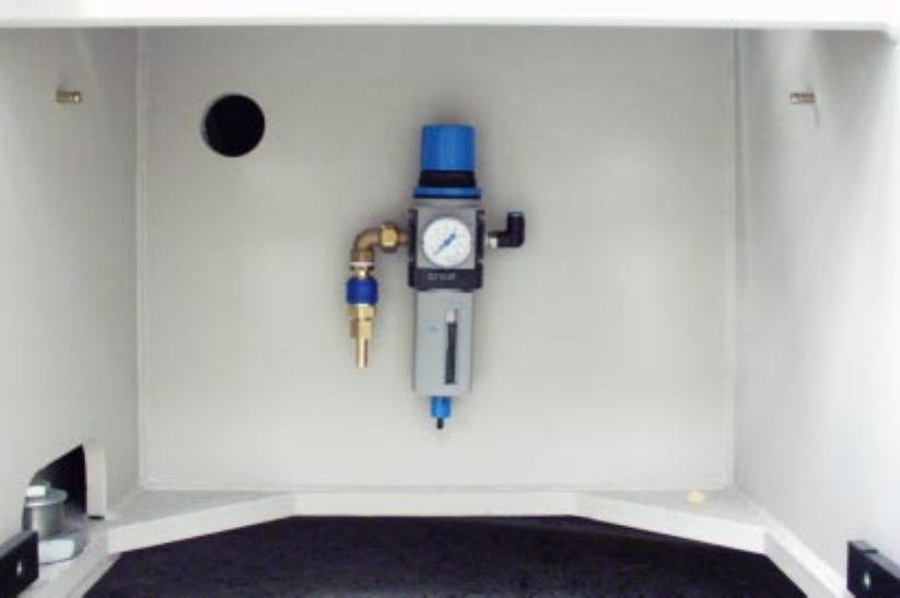
Measure the distance to the intended position for the compressed air distributor, then cut the
compressed air hose to the required length.
:
Connect the hose to the compressed air maintenance unit.
:
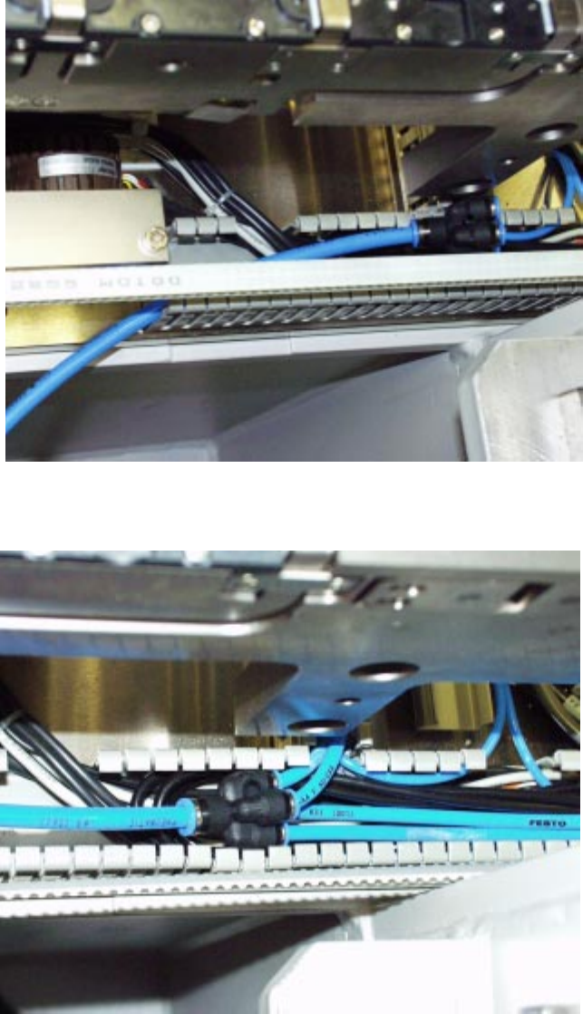
Run the hose up and into the cable duct. It may be necessary to break a tab out of the cable
duct in order to introduce the hose.
(Run the hose as for the ceramic substrate centering unit).
Vacuum Tooling for HS-50 Retrofit Instructions / User Manual
4 Installing the compressed air supply Edition 12/00
40
:
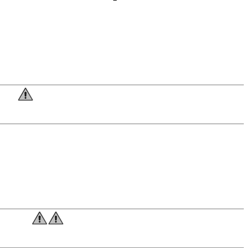
Connect the four vacuum tooling hoses to the compressed air distributor.
: Refit the waste tape chute.
: Move the component cart back into the placement machine.
Retrofit Instructions / User Manual Vacuum Tooling for HS-50
Edition 12/00 5 Preconditions and Restrictions
41
3UHFRQGLWLRQVDQG5HVWULFWLRQV
3UHFRQGLWLRQVIRUWKHXVHRIWKHRSWLRQ
RQSODFHPHQ WPDFKL QH +6
– Use of the option is possible starting with >
No. 1 with dual or single conveyor.
– The position of the sonar proximity switch - and thus the stopper - is limited by the opening in
the tool of the "vacuum tooling" to the middle of the conveyor width.
– The conveyor width must be set to the PCB width to be populated before the option is installed.
The PCB must be moved from loader to unloader without getting stuck and without too much
clearance on the sides.
RQWKHRSWLRQ
– This option must be connected directly to an external compressed air supply.
NOTE
When the option is connected to the compressed air system of the placement machine, its proper
operation is no longer ensured.
– The option must be aligned in X- and Y-position on the lifting table:
– At right angles to the direction of transport: The bottom plate must be placed in the middle
of the lifting table parallel to stationary and movable sides. To do this, the transport width
must first be set to the required width for the work with the option.
– In the direction of transport: The vacuum plate (top plate) of the option has to be positioned
such that the PCB lying against the extended stopper is optimally drawn against the suction
cups.
WARNUNG
The vacuum tooling must be position on the lifting table outside the admissible ranges of distur-
bances. Incorrect positioning can result in damage to the machine (or the PCB)!
– The interfaces of the option have to be connected (see Fig. 3 - 1):
- Interface for electricity: connection see "Circuit Diagrams", Section 10.
- Interface for compressed air: The 5.5 bar compressed air branch in the machine has
to be connected to the option’s vacuum generator.