00192368-01.pdf - 第39页
Retrofit Instructions / User Manual Vacuum Tooling for HS-50 Edition 12/00 4 Instal ling the compressed air supply 39 : Measur e the distance to the intend ed position for the co mpressed air distribu tor , then cut …
Vacuum Tooling for HS-50 Retrofit Instructions / User Manual
4 Installing the compressed air supply Edition 12/00
38
:
Tap an M6x8 thread in the hole.
:
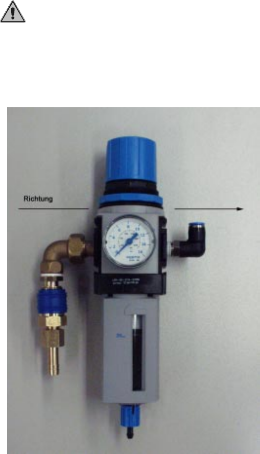
Assemble the compressed air maintenance unit (see photograph below).
The compressed air flows from left to right.
____________________________________________________________________________
PLEASE NOTE
!
Make sure that the air flows through the compressed air maintenance unit in the correct
direction.
___________________________________________________________________________
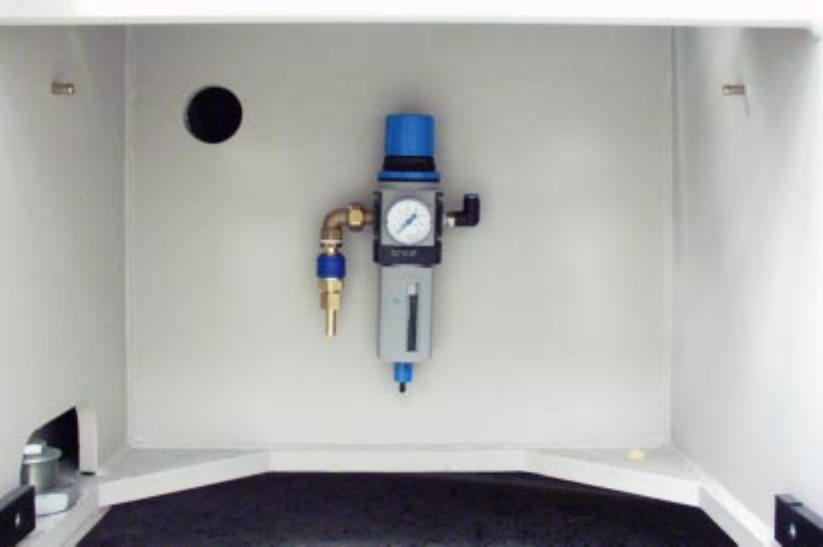
: Use two M6 x 8 fillister head screws to fix the bracket.
Place the compressed air maintenance unit (see photograph below) on the bracket.
Retrofit Instructions / User Manual Vacuum Tooling for HS-50
Edition 12/00 4 Installing the compressed air supply
39
:
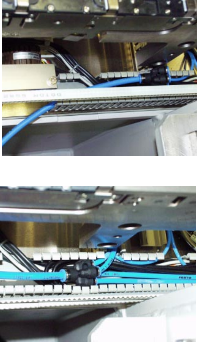
Measure the distance to the intended position for the compressed air distributor, then cut the
compressed air hose to the required length.
:
Connect the hose to the compressed air maintenance unit.
:
Run the hose up and into the cable duct. It may be necessary to break a tab out of the cable
duct in order to introduce the hose.
(Run the hose as for the ceramic substrate centering unit).
Vacuum Tooling for HS-50 Retrofit Instructions / User Manual
4 Installing the compressed air supply Edition 12/00
40
:
Connect the four vacuum tooling hoses to the compressed air distributor.
: Refit the waste tape chute.
: Move the component cart back into the placement machine.