MR-Conveyor-Maintenance-Guide.pdf - 第10页
EN - 0034 Rev. F MR Conveyor Maintenance G uide 10 3/12/2024 Rou tine Maintenance Pulley / Roller Replacement Procedure: 1) Unplug po wer to the Convey or. 2) Loo sen the Shaft from the Rail with a ½ ” wrench. 3) T urn t…

EN-0034 Rev. F MR Conveyor Maintenance Guide 9
3/12/2024
Preventive Maintenance
The following is a list of procedures that should be followed as a part of a regular
maintenance routine.
Procedure For Belt Drive Conveyors:
1) Unplug the Conveyor Power Connector.
2) Check the Conveyor to make sure that all Rollers are turning freely.
3) Check for wear on the Drive Belt and on the Timing Belts.
4) Check to make sure that the Drive Belt is in alignment and properly tensioned.
5) Check to make sure that the Conveyor is securely fastened to its frame.
6) Always hand-power the Conveyor after maintenance and before start-up.
7) Restore Power to the Conveyor.
Procedure For Direct Drive Conveyors:
1) Unplug Power to the Conveyor.
2) Check the Conveyor to make sure that all Rollers are turning freely.
3) Check for wear on the Timing Belts.
4) Check to make sure that the Conveyor is securely fastened to its frame.
5) Always hand-power the Conveyors after maintenance and before start-up.
6) Restore Power to the Conveyor.
EN-0034 Rev. F MR Conveyor Maintenance Guide 10
3/12/2024
Routine Maintenance
Pulley / Roller Replacement
Procedure:
1) Unplug power to the Conveyor.
2) Loosen the Shaft from the Rail with a ½” wrench.
3) Turn the Shaft out with your fingers.
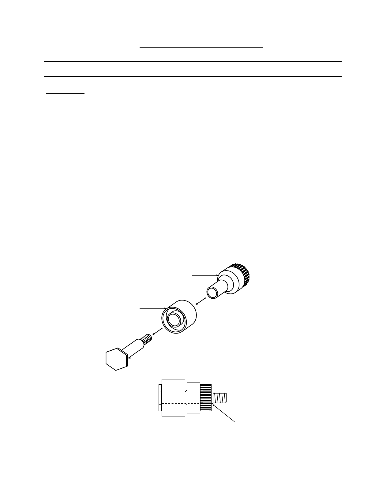
4) Place a new Roller and/or Pulley on the Shaft.
5) Make sure that the shoulder of the Shaft extends past the Pulley to prevent
the Pulley from being pinched against the Rail (See below).
6) Turn the Roller Assembly into the rail with your fingers until snug.
7) Using a Torque Wrench set to 32 inch/pounds, tighten the Roller Assembly.
8) Hand spin the Pulley and Roller to make sure they spin freely and are not
being pinched into the Rail.
9) Restore power to the Conveyor.
Pulley
Roller
Roller Shaft
Roller Assembly Diagram
Make certain that the Roller Shaft’s shoulder extends past the Pulley.
EN-0034 Rev. F MR Conveyor Maintenance Guide 11
3/12/2024
Collar Clamp Removal
Procedure:
1) Unplug power to the Conveyor.
2) Remove the 4-40 x ¼” Socket Head Cap (SHC) Screws from the Collar Clamp.
(2 screws for narrow clamps, 4 screws for wider clamps)
3) Pry the pieces apart using a small, straight-blade screwdriver.
Collar Clamp Assembly
Procedure:
1) Unplug power to the Conveyor.
2) Check the Drive Side and Passive side Pulleys for proper position. The Pulleys
should be against the Rails.
3) Place one Clamp piece on the Pulleys. Be sure that the piece is as close to centered
as possible.
4) Place the other Clamp piece on in alignment with the first piece.
5) Tighten the Collar Clamp in place by using the following procedure:
a) Tighten one 4-40 x ¼” SHC Screw until snug.
b) Tighten the second screw until snug.
c) Fully tighten the first screw.
d) Fully tighten the second screw.
Note: 1.)Three piece clamps use four screws, two at each end. Tighten screws gradually
and evenly while keeping parts centered. Rotate the assembly by hand to check.
2.) Clamps 1.50”— 2.50” use 1 FHCS.
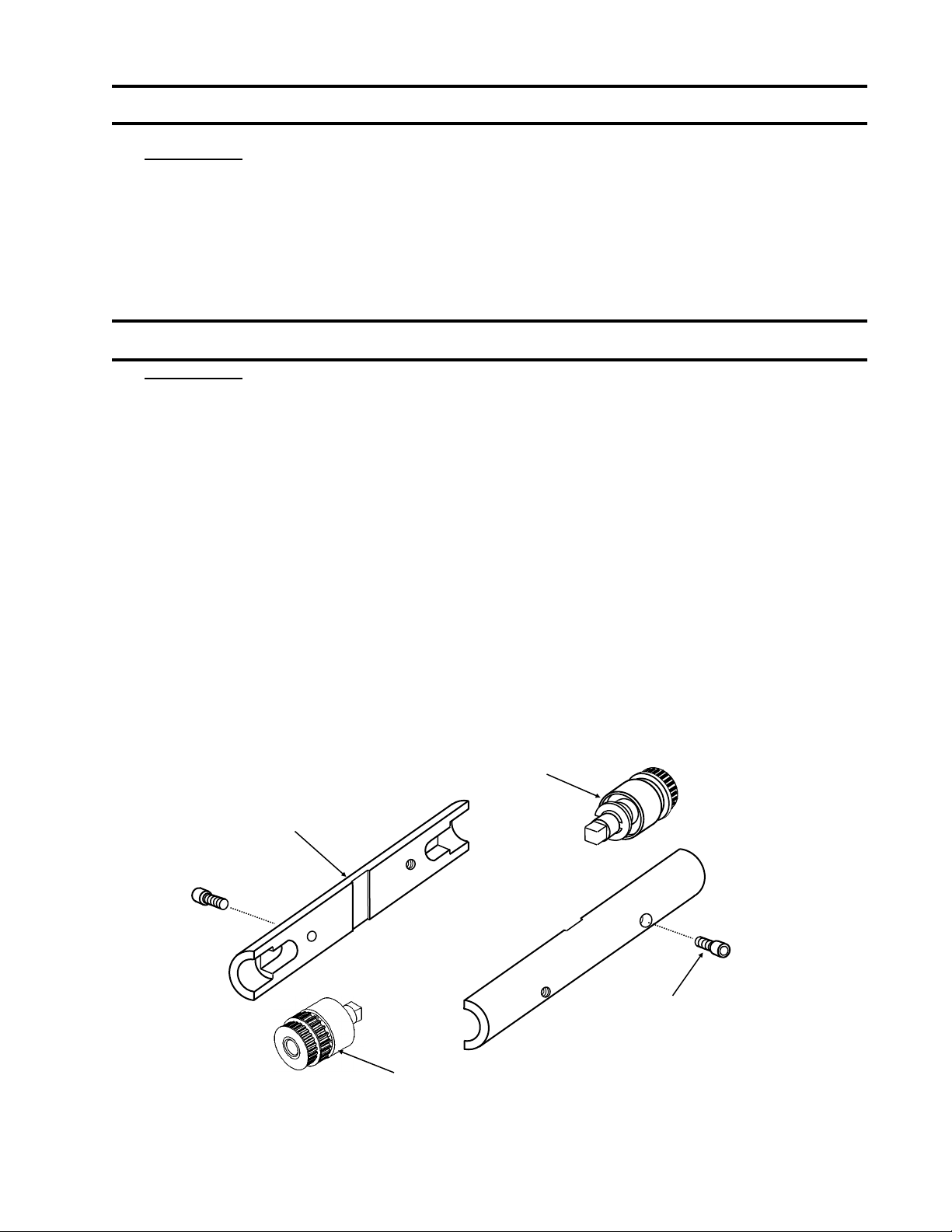
This diagram is of a two piece clamp. Three piece clamps are similar.
Collar Clamp
Passive Roller Assembly
4-40 x ¼” SHC Screw
Drive Roller Assembly
(910314)