MR-Conveyor-Maintenance-Guide.pdf - 第25页
EN - 0034 Rev. F MR Conveyor Maintenance G uide 25 3/12/2024 Setting Con ve y or Speeds Unless otherwise requested, Quickdraw sets all MR Conveyor Speeds at 50 ft./min. for all MR Conveyor Systems that include Conveyor C…
EN-0034 Rev. F MR Conveyor Maintenance Guide 24
3/12/2024
• Motor External Direction mode uses the control signal on P1-11. This pin is brought to
common P1-12 through a jumper wire, switch, relay, or an open collector NPN
transistor.
• Motor Forward mode, the motor will always rotate clockwise (view facing shaft end).
• Motor Reverse mode, the motor will always run counterclockwise.
SPECIFICATIONS:
BOARD OUTSIDE DIMENSION………………………………………………….. 2.3” x 3”
MOUNTING HOLE DIMENSION………………………………………………..... 1.9” x 2.6”
INPUT VOLTAGE …………………………………………………………………. 24Vdc
OUTPUT VOLTAGE ………………………………………………………………. 0 to 24Vdc
MOTOR HALL SPACING (jumper selectable) …………………………………. 60° or 120°
LOAD CURRENT (continuous) …………………………………………………... 2.5 Amps continuous
SPEED RANGE ……………………………………………………………………. 0-100%, full range
INPUT CONNECTIONS …………………………………………………………... 14-pin JST
OUTPUT CONNECTIONS ……………………………………………………….. 9-pin JST
SPEED COMMAND SIGNAL …………………………………………………….. 2-5Vdc
DIRECTIONAL COMMAND SIGNAL ……………………………………………. Switched to common
MOTOR CONTROL SIGNAL …………………………………………………….. Switched to common
OPERATING TEMPERTURE ……………………………………………………. 32° - 95° F
INTERNAL VOLTAGE SUPPLY (for hall sensors) …………………………….. 6.25 Volts
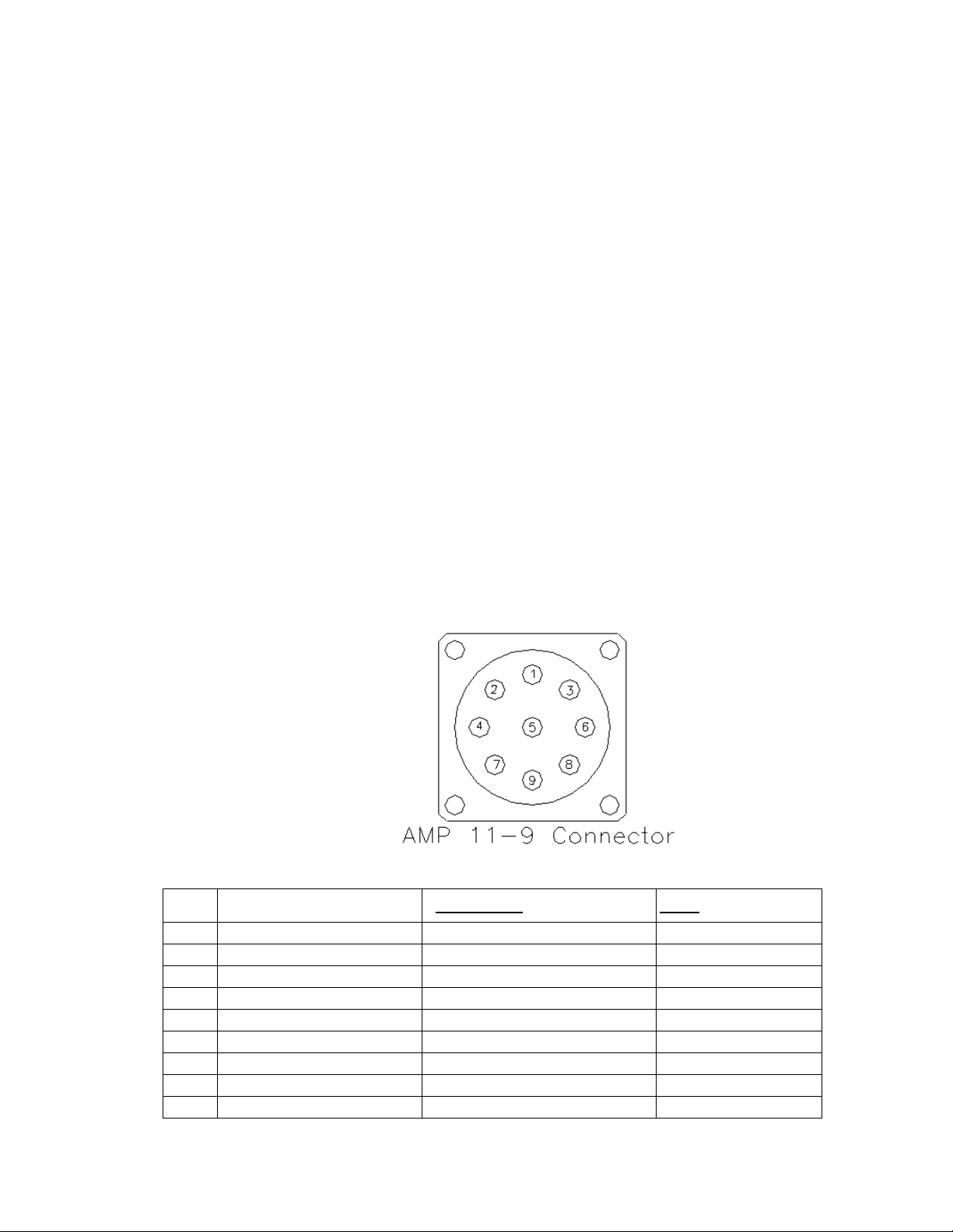
Conveyor Interface Connector:
PIN # DESCRIPTION STANDARD CABLE COLOR FLEX CABLE COLOR
1 +24V Source Orange Pink
2 Motor ON/OFF Brown Brown
3 Motor ON/OFF Common Red Red
4 Motor Direction Black Gray
5 Motor Direction Common White White
6 Speed Reference (0-5VDC) Blue Blue
7 Source Common Green Green
8 N/C X X
9 N/C X X
Quickdraw PN—980413

EN-0034 Rev. F MR Conveyor Maintenance Guide 25
3/12/2024
Setting Conveyor Speeds
Unless otherwise requested, Quickdraw sets all MR Conveyor Speeds at 50 ft./min.
for all MR Conveyor Systems that include Conveyor Control Boxes. Quickdraw does
this to standardize its conveyor performance data. The Motor Cards used on most
applications come with Speed Potentiometers (Speed Pots) that can either be used
or discarded. Most customers choose not to use the Speed Potentiometers, but
rather set speed with Min/Max Speed Pots directly attached to the board.
How To Determine Conveyor Speed
Procedure:
1) Place a piece of non-reflective tape around the Collar Clamp. * This is done to
ensure that the Tachometer is reading only the reflection of the special
reflective tape.
2) Place a small piece of reflective tape onto the other tape.
3) Turn on the conveyor.
4) Measure the rpm with a Handheld Optical Digital Tachometer, such as the
“AMETEK Model 1726 Optical Digital Tachometer”.
How To Convert Linear Distance/Minute to Target RPM
Procedure:
1) Establish the needed conveyor flow rate. * For example: 50 ft/min.
2) Determine the diameter of a Roller. * The diameter of a standard Roller is
0.827”.
3) Use the following formula to determine the target rpm:
Target RPM = Linear Speed (ft/min) / {π*roller diameter (in feet)}
→ Target RPM = 50 ft/min. / π* (0.827”/12”/ft)
→ Target RPM = 50 ft/min. / π* 0.069 ft.
→ Target RPM = 50 ft/min. / 0.217 ft.
→ Target RPM = 231 rpm
Procedure For Conveyors Equipped With Dart 730 BDC Control Cards:
With Speed Pot:
1) Turn the dial on Speed Pot until the tachometer reads target rpm.
2) If unable to achieve target rpm, adjust the white Min and Max dials found on
the Motor Control Card until the target rpm can be achieved within the range of
the Speed Pot.
Without Speed Pot:
1) Adjust the white Min and Max dials found on the Motor Control Card until the
target rpm can be achieved.

EN-0034 Rev. F MR Conveyor Maintenance Guide 26
3/12/2024
Phase Considerations
For most applications, Quickdraw Systems uses low voltage, Brushless DC 3-Phase
Motors and Control Cards. Occasionally, a faulty phase may be the problem.
Signs of a bad phase include but are not limited to:
a) Intermittent Motor Failure.
b) The ability to start the Motor by turning the Collar Clamp or Motor Shaft
after initial powering-up of the Conveyor. After the Motor has been finger
started, the Motor turns on its own, but again may intermittently have a
start up problem.
To remedy this situation, follow the Electrical Troubleshooting guide on the following page.
Make certain to turn the Conveyor on and off multiple times to make sure that the real
cause of the problem is found.