MR-Conveyor-Maintenance-Guide.pdf - 第12页
EN - 0034 Rev. F MR Conveyor Maintenance G uide 12 3/12/2024 Motor Pulley Gauging Important: This procedure is for Belt Drive models. Many problem s can occur if the Motor Pulle y and the Drive Side Pulley are not proper…
EN-0034 Rev. F MR Conveyor Maintenance Guide 11
3/12/2024
Collar Clamp Removal
Procedure:
1) Unplug power to the Conveyor.
2) Remove the 4-40 x ¼” Socket Head Cap (SHC) Screws from the Collar Clamp.
(2 screws for narrow clamps, 4 screws for wider clamps)
3) Pry the pieces apart using a small, straight-blade screwdriver.
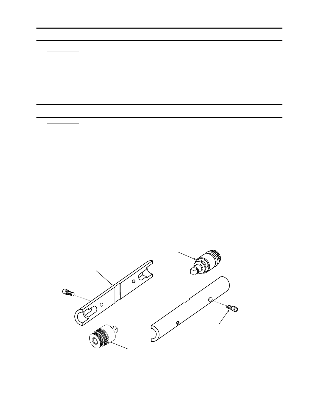
Collar Clamp Assembly
Procedure:
1) Unplug power to the Conveyor.
2) Check the Drive Side and Passive side Pulleys for proper position. The Pulleys
should be against the Rails.
3) Place one Clamp piece on the Pulleys. Be sure that the piece is as close to centered
as possible.
4) Place the other Clamp piece on in alignment with the first piece.
5) Tighten the Collar Clamp in place by using the following procedure:
a) Tighten one 4-40 x ¼” SHC Screw until snug.
b) Tighten the second screw until snug.
c) Fully tighten the first screw.
d) Fully tighten the second screw.
Note: 1.)Three piece clamps use four screws, two at each end. Tighten screws gradually
and evenly while keeping parts centered. Rotate the assembly by hand to check.
2.) Clamps 1.50”— 2.50” use 1 FHCS.
This diagram is of a two piece clamp. Three piece clamps are similar.
Collar Clamp
Passive Roller Assembly
4-40 x ¼” SHC Screw
Drive Roller Assembly
(910314)
EN-0034 Rev. F MR Conveyor Maintenance Guide 12
3/12/2024
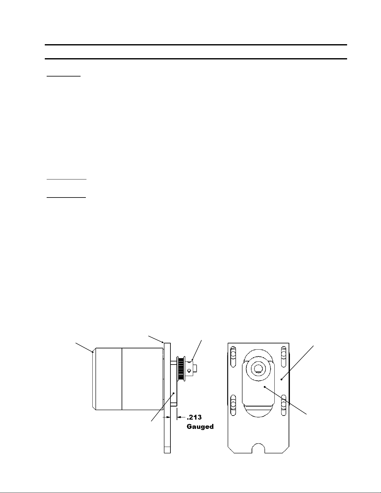
Motor Pulley Gauging
Important: This procedure is for Belt Drive models.
Many problems can occur if the Motor Pulley and the Drive Side Pulley are not properly
aligned. Problems created by running a Conveyor with a poorly aligned Drive Belt include:
1) Worn Drive Components
2) Debris accumulation from pulley wear.
3) Drive Belt breakage
4) Belt noise
5) High current draws
The importance of proper Drive Belt alignment cannot be overstated. Therefore, Motor
Pulleys should be gauged every time that the Drive Belt is removed or whenever it can easily
be gauged as part of another maintenance procedure.
Please Note: Make sure that the proper Gauge is being used.
Procedure:
1) Unplug power to the Conveyor.
2) Remove the Drive Belt (See Page 13).
3) Slide the Gauge (*Not Provided) between the Motor Pulley and the Motor
Mount. If the gauge* slides in and fits snugly, the Motor Pulley is positioned
correctly, skip to procedure number 7. If not, continue to procedure number 4.
4) Loosen the set screw(s) on the Motor Pulley.
5) Slide the Gauge* between the Motor Pulley and the Motor Mount.
6) With the Motor tightly held to the Motor Mount, press the Motor Pulley and
Gauge* to the Motor Mount, tighten the set screw(s).
7) Slide the Gauge* out.
8) Attach the Drive Belt (See Page 13).
9) Visually confirm that the Drive Belt is aligned vertically on the Motor Pulley and
Drive Side Pulley.
Motor
Motor Mount Motor Pulley
Motor Pulley Gauge
Motor Mount
Motor
Pulley
Gauge
*Not Provided

EN-0034 Rev. F MR Conveyor Maintenance Guide 13
3/12/2024
Drive Belt Removal
Procedure:
1) Unplug Power to the Conveyor
2) Remove the Collar Clamp, Drive Side Cover, and Drive Side Product Guide.
3) Remove the Motor Cover.
4) Loosen the four upper Motor mounting screws.
5) Slide the Motor up and remove the Drive Belt from the Motor Pulley.
6) Pull the Drive Side Pulley away from the Rail and off of the Drive Post.
7) Lift the Drive Belt off of the Drive Side Pulley.
Drive Belt Attachment
Procedure:
1) Place the Drive Belt on the Drive Side Pulley.
2) Put the Timing Belt onto the teeth of the Drive Side Pulley.
3) Slide the Drive Side Pulley onto the Drive Post. Turn the Drive Side Pulley with
your fingers to ensure that the Timing Belt is properly seated.
4) Slide the Motor up and put the Drive Belt around the Motor Pulley. Spin the
Pulley until the Belt is properly seated.
5) Gauge the Motor Pulley (See Page 12).
6) To set the Drive Belt tension, see Page 14.
7) Tighten securely using a 9/64”hex wrench and an 11/32” combination wrench.
8) Visually check the Drive Belt alignment.
9) Reassemble the Collar Clamp (See Page 11).
10) Replace the Product Guide.
11) Hand power the Conveyor (See Page 8).
12) Reattach the Cover.
13) Hand power the Conveyor.
14) Reattach the Motor Cover.
15) Turn on the Conveyor.