MR-Conveyor-Maintenance-Guide.pdf - 第22页
EN - 0034 Rev. F MR Conveyor Maintenance G uide 22 3/12/2024 Integra l Motor Contr oller , Cont’d Motor Speed Control: Quickdraw ’ s BLDC controller comes with two speed control options. The different control options can…
EN-0034 Rev. F MR Conveyor Maintenance Guide 21
3/12/2024
Integral Motor Controller
Introduction:
Quickdraw’s brushless DC (BLDC) motor controller commutates power into a standard
three phase brushless (BLDC) motor up to a 10-watt motor. The BLDC controls (i.e.
speed, direction, enabling) can be set by using jumpers or by giving external signals to
connector P1.
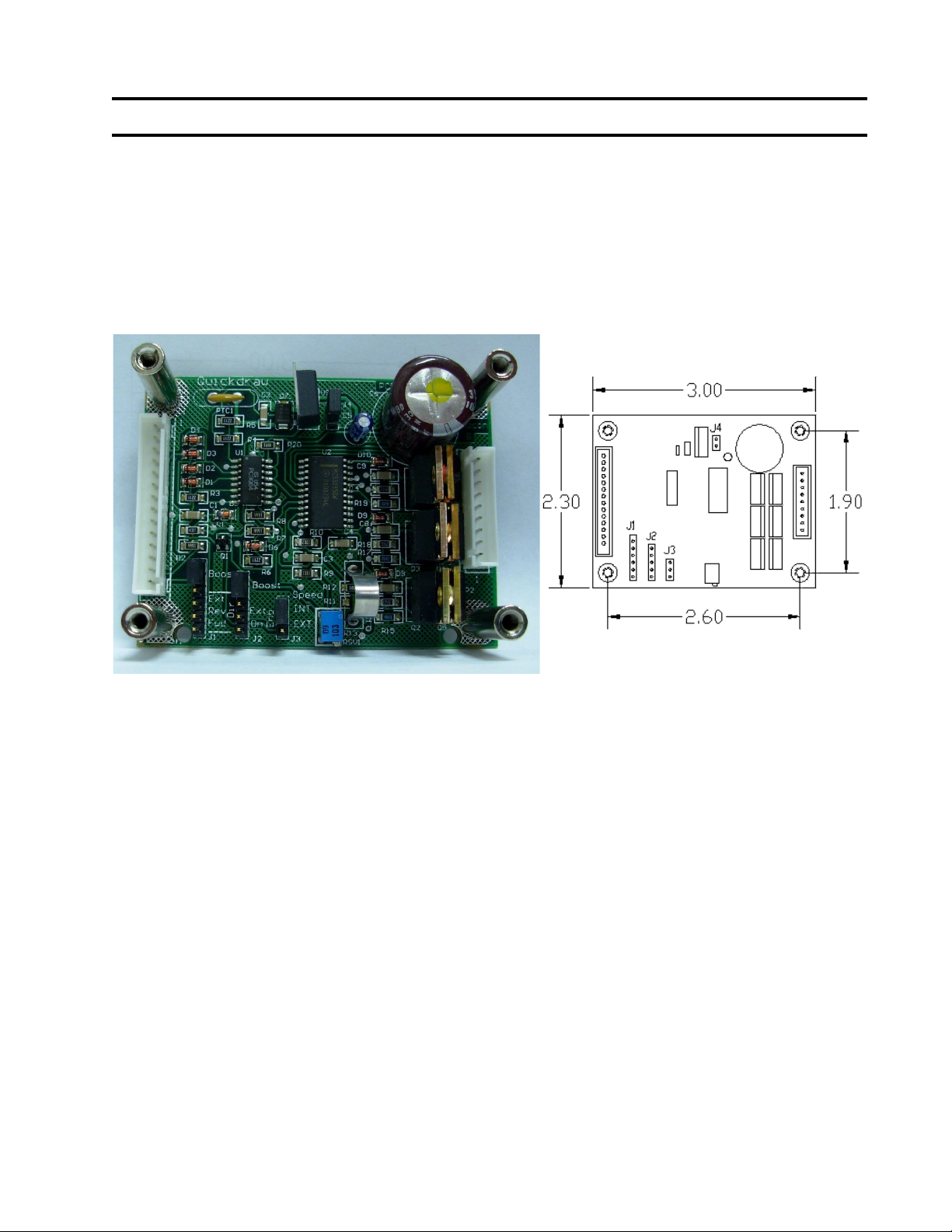
Controller Dimension Diagram
6-32 tapped standoff on board
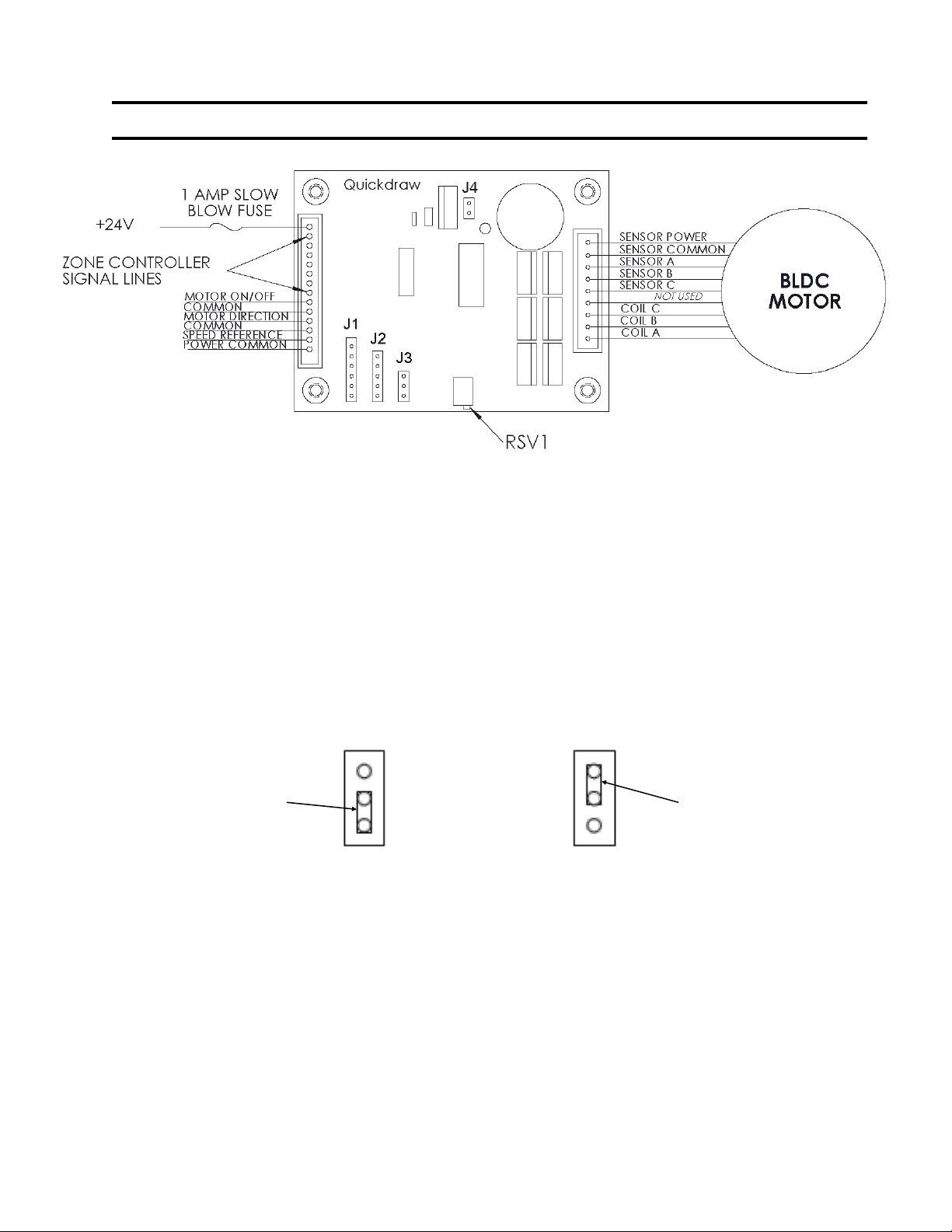
Connections: Power and Control Signals, Brushless Motors and Hall Sensors.
Brushless Motors:
Brushless DC motors have eight (8) wires; three (3) phase lines to the motor, three (3) Hall sensor
lines, and sensor power and common. Also BLDC motors come with two sensor configurations.
60, and 120 degrees and is connected to P2.
Quickdraw designed this controller to power Japan servo 3W and 10W motors, although other
motors can be driven with this controller.
Motor Sensor Spacing:
Quickdraw’s BLDC controller is shipped ready for 120-Degree sensor spacing. (Note: The Japan
Servomotors supplied on most Quickdraw conveyors use 120 Degree sensor spacing) However, if
60-degree spacing is desired, remove the jumper across J4.
Power Requirements:
The power is supplied to this card using Pin 1 and Pin 14 on connector P1. The 24V input signal
should be fused with a 1-amp slow blow fuse. The power should be off until the hookup procedure
is complete and you are ready to run.
EN-0034 Rev. F MR Conveyor Maintenance Guide 22
3/12/2024
Integral Motor Controller, Cont’d
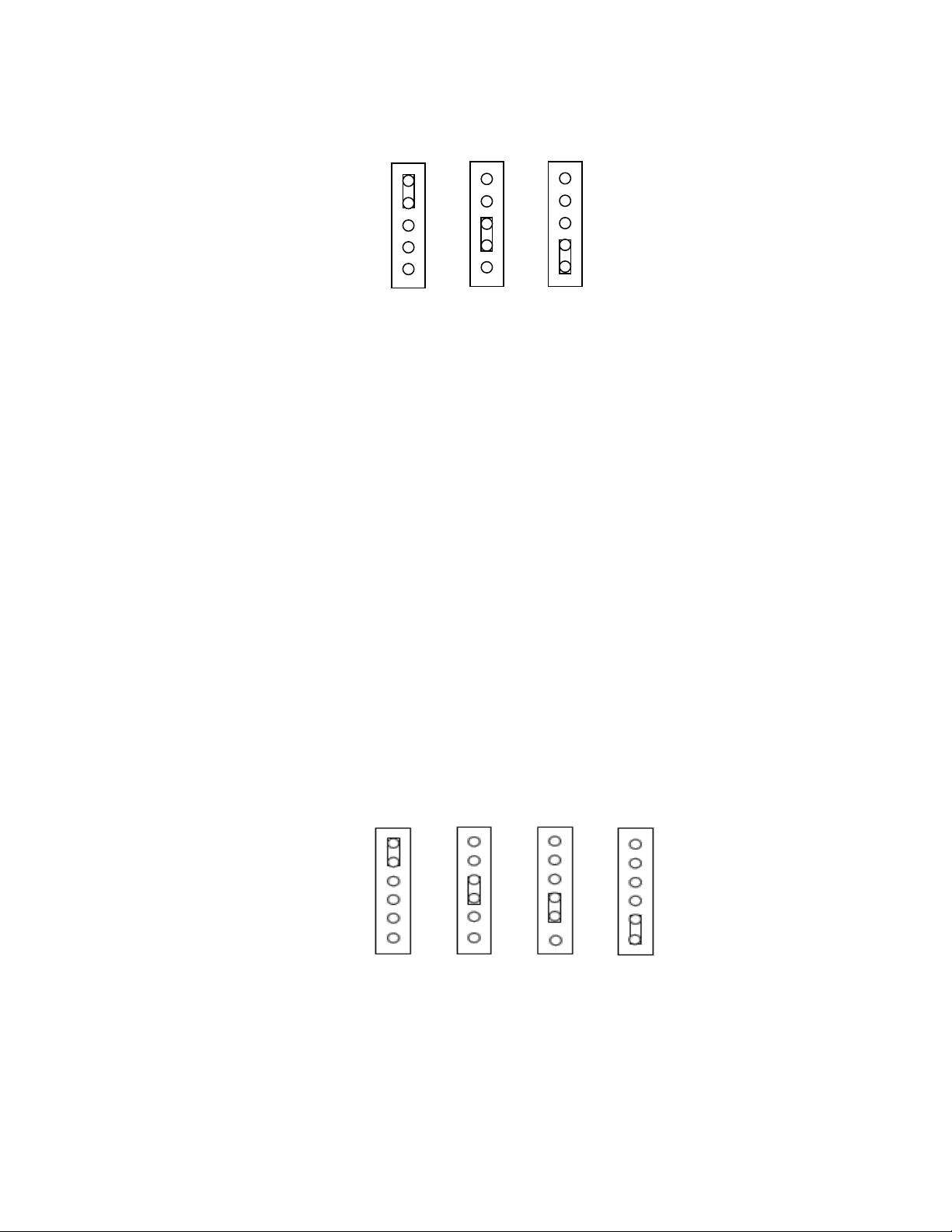
Motor Speed Control:
Quickdraw’s BLDC controller comes with two speed control options. The different control
options can be selected by changing the position of jumper J3 on the motor controller
board. When internal speed control is selected with the jumpers, the motor references the
multi turn pot (RSV1) on the controller board for speed. The speed can be increased or
decreased by turning the pot with a non-conducting screwdriver.
When the external speed control is selected, the speed pot is disabled and the motor gets
its speed reference from an external 2-5V signal. This signal should be reference to the
controller’s common.
Motor Controller speed control options.
J3 J3
Jumper
Jumper
External Internal
(Default Setting)
EN-0034 Rev. F MR Conveyor Maintenance Guide 23
3/12/2024
• Motor direction is specified by the Customer.
• Motor Boost mode uses directional control signals from another controller and
amplifies those signals for use on higher wattage motors. These connections are
made through P1.
Boost External Enable
Enable
(Default Setting)
Motor Controller Enabling Options.
J2 J2 J2
Motor Enabling Control:
Quickdraw’s BLDC controller has three modes for controlling the motor: boost, external
enable, and always on.
Motor Boost mode uses control signals from another controller and amplifies those signals
for use on higher wattage motors. These connections are made through P1.
Motor External Enable mode uses the control signal on P1-9. This pin is brought to
common P1-10 through a jumper wire, switch, relay, or an open collector NPN transistor.
Motor Enable mode; the motor is always on.
Unless specified otherwise by the customer, the default setting for this jumper is “External
Enable”.
Motor Directional Control:
Quickdraw’s BLDC controller has four modes for controlling the motor direction: boost,
external direction, always forward, or always reverse. This controller is not designed for
plug reversing. Damage to the controller could happen by not stopping it first.
It may be necessary to reverse the motor without changing the directional controls. This
can be accomplished by changing P2-1 with P2-3 and P2-6 with P2-5.
Boost External Rev. For.
Direction
Motor Controller Directional options.
J1 J1 J1 J1