MR-Conveyor-Maintenance-Guide.pdf - 第20页
EN - 0034 Rev. F MR Conveyor Maintenance G uide 20 3/12/2024 Electrical Contr ols Maintenanc e Measuring Cur rent Draw Procedure: Warning: This procedure describes testing in an open, powered Control Panel. Use caution. …
EN-0034 Rev. F MR Conveyor Maintenance Guide 19
3/12/2024
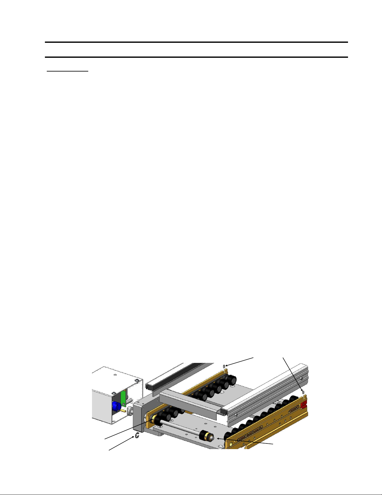
Direct Drive Timing Belt Replacement - Either Side
Procedure :
1) Unplug power to the Conveyor.
2) Remove both of the Side Covers and Product Guides.
3) Remove the Motor and Cover (See Page 16).
4) Remove the Collar Clamp Guard.
5) Loosen both setscrews at the Belt Tensioners to relax the Timing Belts.
6) Remove the drive side E-Ring on the Drive Shaft.
7) Loosen the setscrew that locks the drive side Pulley to the Drive Shaft.
8) Slide the Drive Shaft out the Motor side of the Conveyor just enough to slip the
Timing Belt past the passive end Pulley and Shaft end. You may now remove
either Timing Belt.
9) Check the Pulleys for wear.
10) Slip the replacement Timing Belt over the Drive shaft and reinstall the Drive
Shaft into the Passive Pulley and passive side Bearing.
11) Position the Drive Shaft end flush with the passive side outside Rail face.
12) Slide the Drive Pulley back in to position in line with all Pulleys and tighten the
setscrew onto the flat on the Drive Shaft.
13) Reinstall the drive side E-Ring.
14) Make sure the Belt teeth are fully engaged in the Pulley teeth and then set the
Timing Belt Tension and tighten those setscrews (See Page 14).Rotate the
Drive Shaft by hand to confirm full tooth engagement.
15) Reinstall the Motor and Cover (See Page 16).
16) Reinstall the Product Guides and Rail Covers. Rotate the Drive Shaft to
maintain Belt tooth engagement as these parts are installed.
17) Reinstall the Collar Clamp Guard.
18) Rotate the Conveyor by hand (See Page 8).
19) Turn on the Conveyor.
E-Ring
Setscrews
Setscrew
Slip Belt around
this end.
EN-0034 Rev. F MR Conveyor Maintenance Guide 20
3/12/2024
Electrical Controls Maintenance
Measuring Current Draw
Procedure:
Warning: This procedure describes testing in an open, powered Control Panel.
Use caution.
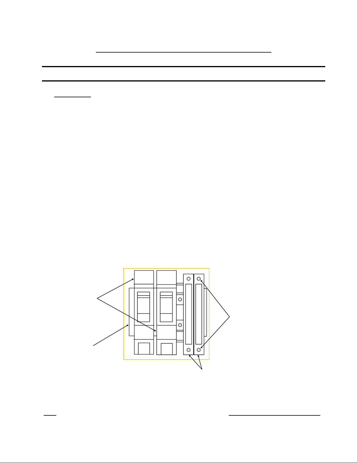
1) In the Control Panel, open the Fuse Cover on the Fuse segment for that
specific Conveyor. Opening the cover removes the fuse from the circuit.
2) With power on, carefully place the ammeter’s Probes on the screw heads as
indicated in the diagram. The conveyor will “turn on”. Take a reading on the
meter.
3) If the reading is negative, reverse the probes.
4) The reading on a standard MR conveyor (unloaded - no product or pallet
resistance) should be less than or equal to 0.50 amps.
5) If the reading exceeds this, see the Trouble Shooting -High Current section of
this Manual (Page 29).
6) Remove the Ammeter and close the Fuse segment cover. Close the Control
Panel cover.
Note: Quickdraw Conveyors with a standard 10W Motor should draw no more than 0.50 amps unloaded.
Breakers
DIN Rail
Fuse Holders
Screw Heads
(Electrical Contacts)
Example of Breakers and Fuse Holders mounted on DIN
Rail inside a control Panel.
EN-0034 Rev. F MR Conveyor Maintenance Guide 21
3/12/2024
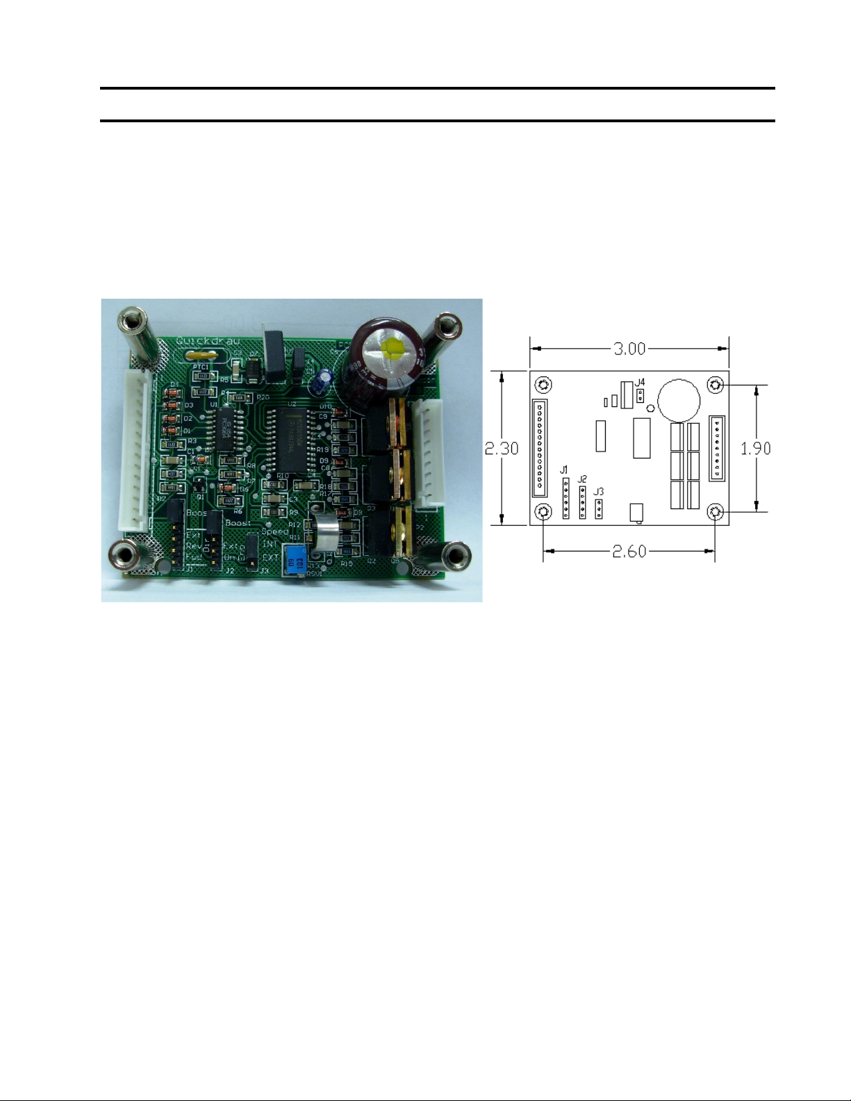
Integral Motor Controller
Introduction:
Quickdraw’s brushless DC (BLDC) motor controller commutates power into a standard
three phase brushless (BLDC) motor up to a 10-watt motor. The BLDC controls (i.e.
speed, direction, enabling) can be set by using jumpers or by giving external signals to
connector P1.
Controller Dimension Diagram
6-32 tapped standoff on board
Connections: Power and Control Signals, Brushless Motors and Hall Sensors.
Brushless Motors:
Brushless DC motors have eight (8) wires; three (3) phase lines to the motor, three (3) Hall sensor
lines, and sensor power and common. Also BLDC motors come with two sensor configurations.
60, and 120 degrees and is connected to P2.
Quickdraw designed this controller to power Japan servo 3W and 10W motors, although other
motors can be driven with this controller.
Motor Sensor Spacing:
Quickdraw’s BLDC controller is shipped ready for 120-Degree sensor spacing. (Note: The Japan
Servomotors supplied on most Quickdraw conveyors use 120 Degree sensor spacing) However, if
60-degree spacing is desired, remove the jumper across J4.
Power Requirements:
The power is supplied to this card using Pin 1 and Pin 14 on connector P1. The 24V input signal
should be fused with a 1-amp slow blow fuse. The power should be off until the hookup procedure
is complete and you are ready to run.